
Related Manuals for Promise Technology VTrak J610s


Summary of Contents for Promise Technology VTrak J610s
- Page 1 J610s, J310s UICK TART UIDE Version 1.0 © 2007 Promise Technology, Inc. All Rights Reserved.
-
Page 2: Vtrak Task List
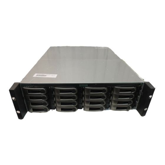
Step 5: Setting Up Serial Cable Connections (page 20) Step 6: Connecting the Power (page 21) Step 7: Setting Up the CLI Connection (page 22) Step 1: Unpacking the VTrak The VTrak J610s or J310s box contains the following items: • VTrak J610s or J310s Unit •... - Page 3 Step 1: Unpacking the VTrak Figure 1. VTrak J610s front view with bezel removed Drive Carrier LEDs Drive Carriers Power and Status LEDs Figure 2. VTrak J610s rear view I/O module 1 I/O module 2 115200 115200 8 N 1...
- Page 4 VTrak J610s, J310s Quick Start Guide Figure 4. VTrak J310s rear view Power Supply 2 Power Supply 1 Cooling Unit 2 Cooling Unit 1 115200 115200 8 N 1 8 N 1 I/O module 1 I/O module 2 Some J610s and J310s units ship with a single I/O module and a dummy module...
- Page 5 VTrak J610s The J610s subsystem installs to the rack using the supplied mounting rails. You can also use your existing rails. Figure 5. VTrak J610s mounted in a rack with the supplied rails Vertical Rack Post VTrak J610s Mounting rails (included)
- Page 6 VTrak J610s, J310s Quick Start Guide Attach the mounting rail assemblies to the outside of the rack posts, using the attaching screws from your rack system. Be sure the support is on the bottom facing inward. Square the rail assemblies in the rack.
- Page 7 Step 2: Mounting VTrak Unit in a Rack VTrak J310s The J310s subsytem installs to the rack using the supplied mounting rails. You can also use your existing rails. Figure 7. VTrak J310s mounted in a rack with the supplied rails VTrak J310s Vertical Rack Post Handles mount...
- Page 8 VTrak J610s, J310s Quick Start Guide The rail is designed to slide freely over the plate. Attach a flange to each end of the rail, with the rail on the opposite side of the flange from the two-hole bracket. Install the rail adjustment screws (included) through the flange into the rail.
- Page 9 Step 2: Mounting VTrak Unit in a Rack Figure 9. Mounting rail installation Rack front post Rack back post Rail adjustment screw Mounting Rail Sliding plate Rail attaching screw Rail attaching screw (not included) (not included) Inside of post Inside of post...
-
Page 10: Step 3: Installing Disk Drives
VTrak J610s, J310s Quick Start Guide Step 3: Installing Disk Drives Populate the VTrak with 3.5-inch SAS or SATA disk drives. Install all of the drive carriers into the J610s or J310s enclosure to ensure proper airflow, even if you do not populate all the carriers with disk drives. - Page 11 Step 3: Installing Disk Drives If you installed an AAMUX, lay the SATA disk drive in the carrier and slide it so the power and data connectors insert in to the AAMUX. See Figure 10 on page 12. Insert the screws through the holes in the drive carrier and into the bottom of the disk drive (see Figure 5).
- Page 12 • A VTrak J610s or J310s carrier is similar in appearance but is NOT interchangeable with a VTrak M500f/i/p drive carrier. Important Be sure each drive is securely fastened to its carrier. Proper installation ensures adequate grounding and minimizes vibration.
-
Page 13: Drive Numbering
Each disk drive in the J610s and J310s units is identified by a number that corresponds to the Port number used for management. For more information, see Chapter 3 of the VTrak J610s, J310s Product Manual on the CD. Numbers are stamped above each drive bay for easy indentification. - Page 14 Under SAS specifications, both I/O modules are active at the same time. The terms primary and secondary are for enclosure management purposes only. To verify which I/O module is the default primary, see Chapter 3 of the VTrak J610s, J310s Product Manual on the CD.
- Page 15 Step 4: Setting Up Data Cable Connections Figure 17.VTrak J610s and J310s I/O modules have one subtractive-routed port and one table-routed port 115200 8 N 1 Table Connector (CN2) LED Subtractive Connector (CN1) LED I/O Module Status LED Each I/O module has one subtractive-routed external receptacle (CN1) and one table-routed external receptacle (CN2).
-
Page 16: Basic Das Connection
VTrak J610s, J310s Quick Start Guide Basic DAS Connection Figure 18. An example of a basic DAS connection between one Host PC and one VTrak J310s unit. The J610s is similar Subtractive-Routed Port 115200 115200 8 N 1 8 N 1... -
Page 17: Cascading Das Connection
Step 4: Setting Up Data Cable Connections Cascading DAS Connection If you are using multiple J610s or J310s units and want to manage them from the same SAS HBA card, connect the J610s or J310s units in a cascade. Connect the SAS HBA card in the Host PC to the subtractive-routed port (CN1) of the I/O module. -
Page 18: Redundant Das Connection
VTrak J610s, J310s Quick Start Guide Redundant DAS Connection The arrangement below is a DAS system with full redundancy. Figure 20. An example of a redundant DAS connection between two Host PCs and four cascaded VTrak J310s units. The J610s is similar... - Page 19 Step 4: Setting Up Data Cable Connections The arrangement requires J610s or J310s units with dual I/O modules and two Host PCs with a SAS HBA card in each PC. Connect the SAS HBA card in the first Host PC to the subtractive-routed port (CN1) on a I/O module of the first J610s or J310s unit.
-
Page 20: Step 5: Setting Up Serial Cable Connections
See “Step 4: Setting Up Data Cable Connections” on page 14 for an explanation of which I/O module is the default primary. To verify which I/O module is the default primary, see Chapter 3 of the VTrak J610s, J310s Product Manual on the... -
Page 21: Step 6: Connecting The Power
I/O module LEDs flash green if there is activity on that connection. There are two LEDs on each Drive Carrier. They report the presence of power and a disk drive, and the current condition of the drive. Figure 23.VTrak J610s/J310s disk carrier LEDs Disk Status Power/Activity Within one minute, the Power/Activity should display Green. -
Page 22: Step 7: Setting Up The Cli Connection
VTrak J610s, J310s Quick Start Guide Step 7: Setting Up the CLI Connection The J610s or J310s unit has a Command Line Interface (CLI) to manage all of its functions, including customization. Access the CLI via your PC’s terminal VT100 or ANSI emulation program, such as Microsoft HyperTerminal. -
Page 23: Frequently Asked Questions
Depending on the nature of the failure, the failed drive the drive might not appear in the CLI, or the failed drive might appear with an error, when you run the enclosure command or the link command. See the VTrak J610s, J310s Product Manual on the CD for more information. -
Page 24: Contact Technical Support
VTrak J610s, J310s Quick Start Guide Contact Technical Support Promise Technical Support provides several support options for Promise users to access information and updates. We encourage you to use one of our electronic services, which provide product information updates for the most efficient service and support. - Page 25 +31 (0) 40 256 9463 Attn: Technical Support Phone Technical Support +31 (0) 40 235 2600 If you wish to write us for Promise Technology Europe B.V. support: Attn: Technical Support Science Park Eindhoven 5542 5692 EL Son, The Netherlands...
- Page 26 VTrak J610s, J310s Quick Start Guide Taiwan E-mail Support support@promise.com.tw Fax Technical Support +886 3 578 2390 Attn: Technical Support Phone Technical Support +886 3 578 2395 (ext. 8811) If you wish to write us for Promise Technology, Inc. support: Attn: Technical Support 2F, No.
Need help?
Do you have a question about the VTrak J610s and is the answer not in the manual?
Questions and answers