Table of Contents
Advertisement
Rating:
Amperes:
Speed:
Weight:
Need Assistance?
Call us on our toll free customer support line:
1-866-349-8665
Technical questions
Replacement parts
Parts missing from package
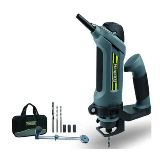
5.8 AMP. CUT-OUT SAW
PRODUCT SPECIFICATIONS
120 V, 60 Hz AC
5.8 Amp.
10,000 – 30,000 RPM (no load)
3 lb 3 oz (1.45 kg)
241-0968
Owner's Manual
Advertisement
Table of Contents

Subscribe to Our Youtube Channel
Related Manuals for Performax 241-0968


Summary of Contents for Performax 241-0968
-
Page 1: Product Specifications
5.8 AMP. CUT-OUT SAW 241-0968 Owner’s Manual PRODUCT SPECIFICATIONS Rating: 120 V, 60 Hz AC Amperes: 5.8 Amp. 10,000 – 30,000 RPM (no load) Speed: Weight: 3 lb 3 oz (1.45 kg) Need Assistance? Call us on our toll free customer support line: 1-866-349-8665 ... -
Page 2: Table Of Contents
TABLE OF CONTENTS Product specifications ………….……………………………………………………. Table of contents ……………………………………………………………………... General safety warnings …………………………………………………………….. 3–4 Eye, ear & lung protection …………………………………………………………… 3–4 Electrical safety ………………………………………………………………………. Power tool safety ……………………………………………………………………... 5–6 General safety rules ………………………………………………………………….. Work area ………………………………………………………………….………….. Electrical safety ………………………………………………………………………. Personal safety ……………………………………………………………………….. -
Page 3: General Safety Warnings
GENERAL SAFETY WARNINGS WARNING: Before using this tool or any of its accessories, read this manual and follow all Safety Rules and Operating Instructions. The important precautions, safeguards and instructions appearing in this manual are not meant to cover all possible situations. It must be understood that common sense and caution are factors which cannot be built into the product. -
Page 4: Electrical Safety
GENERAL SAFETY WARNINGS WEAR A DUST MASK THAT IS DESIGNED TO BE USED WHEN OPERATING A POWER TOOL IN A DUSTY ENVIRONMENT. WARNING: Dust that is created by power sanding, sawing, grinding, drilling, and other construction activities may contain chemicals that are known to cause cancer, birth defects, or other genetic abnormalities. -
Page 5: Power Tool Safety
POWER TOOL SAFETY WARNING: Read all safety warnings When operating a power tool outdoors, and instructions. Failure to follow the use an extension cord suitable for warnings and instructions may result in outdoor use. Use of a cord suitable for electric shock, fire and/or serious injury. -
Page 6: Power Tool Use And Care
POWER TOOL SAFETY PERSONAL SAFETY – cont’d Do not overreach. Keep proper footing Maintain power tools. Check for and balance at all times. This enables misalignment or binding of moving better control of the power tool in parts, breakage of parts and any other unexpected situations. -
Page 7: Specific Safety Rules
SPECIFIC SAFETY RULES WARNING: Always make sure the work surface is free Know your cut-out saw. Read the Owner’s Manual from nails and other foreign objects. carefully. Learn the tool’s applications Cutting into a nail can cause the bit and the tool to jump and damage the bit. -
Page 8: Extension Cord Safety
EXTENSION CORD SAFETY WARNING: Keep the extension MINIMUM GAUGE (AWG) cord clear of the working area. Position EXTENSION CORDS (120V use only) the cord so it will not get caught on the Amperage workpiece, tools or any other obstructions rating Total length while you are working with the power tool. -
Page 9: Symbols
SYMBOLS WARNING: Some of the following symbols may appear on the cut-out saw. Study these symbols and learn their meaning. Proper interpretation of these symbols will allow for more efficient and safer operation of this tool. Direct current Volts Amperes No load speed Alternating or direct Hertz... -
Page 10: Know Your Cut-Out Saw
KNOW YOUR CUT-OUT SAW ON/OFF switch Speed control wheel Hanging loop Side assist handle Circle cutting Spindle locking knob button Freehand cutting guide collar Pivot point Locking knob Collet nut Locking lever Freehand guide foot Circle cutting Pivot point Mounting disc guide Mounting insert... -
Page 11: Contents
CONTENTS CONTENTS CUT-OUT SAW COMPONENTS DESCRIPTION Carefully unpack the cut-out saw. Cut-out saw Compare the contents against the “CUT- Side assist handle OUT SAW COMPONENTS” chart at right. Freehand cutting guide Circle cutting guide NOTE: See illustration of the cut-out saw with installation below. -
Page 12: Assembly And Operating
ASSEMBLY AND OPERATING WARNING: Remove the plug from the power source before assembly, changing accessories or cutters and making adjustments. This will prevent accidental starting of the tool which could result in serious injury. INSTALLING THE ASSIST HANDLE The removable assist handle is designed for use when precision control over the tool movement is desired. -
Page 13: Installing The Freehand Cutting Guide
ASSEMBLY AND OPERATING INSTALLING THE FREEHAND CUTTING GUIDE The freehand cutting guide is designed for basic freehand cutting with the cutting bit. It is ideally suited for cutting electrical outlet holes in drywall. WARNING: Do NOT use the freehand cutting guide with router bits. The amount of control this accessory provides is insufficient and could cause you to lose control and cause serious... - Page 14 ASSEMBLY AND OPERATING INSTALLING CUTTING BITS – cont’d Depress the shaft locking button (1) and rotate the collet lock nut (2) with the other hand until the locking button drops into place, preventing the shaft from turning (Fig. 3). While continuing to hold the shaft locking button IN, use the collet wrench (3) to turn the collet nut counter-clockwise.
-
Page 15: Changing The Collet
ASSEMBLY AND OPERATING CHANGING THE COLLET The cutting bits for this tool are locked into place with a collet nut (1) and collet (2) (Fig. 4). 1/8" and 5/32" collets are used for holding 1/8" and 5/32" cutting bits and hobby tool accessory bits. -
Page 16: On/Off Switch
ASSEMBLY AND OPERATING ON/OFF SWITCH This cut-out saw is equipped with a convenient ON/OFF switch (1) located on the top of the tool handle (Fig. 5). To turn the switch ON, slide the switch outward. To turn the switch OFF, slide the switch inward. - Page 17 ASSEMBLY AND OPERATING ADJUSTING THE FREEHAND CUTTING GUIDE – cont’d Before starting to cut, double check the bit depth. Make sure the cutting guide is at a right angle to the bit and securely tightened. Double check the collet to make sure the bit is securely fastened.
-
Page 18: Cutting Bit Applications
ASSEMBLY AND OPERATING CUTTING BIT APPLICATIONS Recommended Speed control Cut Feet per Cutting Bit Type Material and Thickness wheel setting Minute Fiberglass and laminate up 1/4" (soft wood*, to 1/4" and soft wood* up to 3–6 1 ft./min fiberglass and laminate) 1"... -
Page 19: Practice Cuts Using Freehand Cutting Guide
ASSEMBLY AND OPERATING PRACTICE CUTS USING THE FREEHAND CUTTING GUIDE Before attempting to work on an actual project, take the time to make a few practice cuts with your cut-out saw. Use some scraps of material that are the same material as will be used in your actual project. -
Page 20: Cutting Tips
ASSEMBLY AND OPERATING PRACTICE CUTS USING THE FREEHAND CUTTING GUIDE – cont’d When the motor is up to full speed, slowly tip the tool to an upright position, letting the bit cut into the workpiece (Fig. 9). Once the tool has reached the upright position and the bit has cut through the workpiece, slowly move the tool in a clockwise... - Page 21 ASSEMBLY AND OPERATING CUTTING TIPS – cont’d Slower cutting gives you better control. Excessive pressure or fast cutting will increase the bit temperature and shorten the life of the bit. When cutting a hole in a vertical surface, avoid ending the cut at the bottom of the hole.
- Page 22 ASSEMBLY AND OPERATING CUTTING OUTLET OPENINGS IN DRYWALL – cont’d When fastening the drywall in place, do not place nails or screws closer than 12" from the box. This will prevent the drywall from becoming deformed under pressure. Install the assist handle, freehand cutting guide and cutting bit, as outlined in Fig.
-
Page 23: Installing The Circle Cutting Guide
ASSEMBLY AND OPERATING CUTTING OUTLET OPENINGS IN DRYWALL – cont’d 10. The completed electrical box cut out will be accurately and neatly cut (Fig. 11). NOTE: Always move the cutting bit in a counter- clockwise direction around the outlet box. The natural tendency of the cutting bit to move to the left will make it easier to cut close to the box. -
Page 24: Circle Cutting Guide Operation
ASSEMBLY AND OPERATING INSTALLING THE CIRCLE CUTTING GUIDE – cont’d Screw the internally threaded circle cutting guide mounting disc (6) onto the externally threaded circle cutting guide mounting insert and hand tighten. NOTES: a) Make sure the boss (7) on the cutting guide mounting disc goes through the hole in the circle guide. - Page 25 ASSEMBLY AND OPERATING CIRCLE CUTTING GUIDE OPERATION – cont’d Adjust the circle cutting guide radius by loosening the pivot point knob, sliding it to the correct circle radius and re-tightening in the desired location. NOTE: Check the circle cutting guide radius setting by measuring from the pivot point to the outside of the spiral bit.
-
Page 26: Maintenance
MAINTENANCE Remove accumulated dust and debris GENERAL regularly using a soft DRY brush. WARNING: When servicing, use It has been found that electric tools are only identical replacement parts. The subjected to accelerated wear and use of any other part may create a possible premature failure when they are hazard or cause product damage. -
Page 27: Exploded View
EXPLODED VIEW... -
Page 28: Parts Listing
PARTS LIST WARNING: When servicing, use only original equipment replacement parts. The use of any other parts may create a safety hazard or cause damage to the cut-out saw. Any attempt to repair or replace electrical parts on this cut-out saw may create a safety hazard unless repairs are performed by a qualified technician. - Page 29 PARTS LIST Key # Part # Part Name Quantity 2040140007 Bakelite ball 2030030014 Ruler 3150100001 Round nut 1160030002 Positioning knob 4060020001 Square nut 3140080001 Protection sleeve 2050080075 Flying rings 3120110009 Switch button 1061150001 Switch 3150020005 cord clamp 3140010014 cord guard 1190030006 AC cord &...
-
Page 30: Warranty
® back to your nearest MENARDS™ retail store. At its discretion, PERFORMAX agrees to have the tool or any defective part(s) repaired or replaced with the ®...
Need help?
Do you have a question about the 241-0968 and is the answer not in the manual?
Questions and answers