Table of Contents
Advertisement
Quick Links
Download this manual
See also:
User Manual
Advertisement
Table of Contents

Related Manuals for Galaxy Audio ANY SPOT


Summary of Contents for Galaxy Audio ANY SPOT
- Page 2 System Components.........1 TRC Receiver Features........2 HH64 Handheld Transmitter.......3 MBP64 Body Pack Transmitter......4 System Setup............5 Rack-Mounting the Receivers......6 Tips for Improving System Performance.....7 Troubleshooting..........7 Specifications............8...
- Page 3 Congratulations! Welcome to the AS-TRC wireless mic system. To users who need to build an advanced UHF wireless system, the AS-TRC provides an excellent solution. With 120 frequency choices, the AS-TRC is Ideal for various wireless applications such as live shows, broadcast, meetings, instrument pickups, etc.
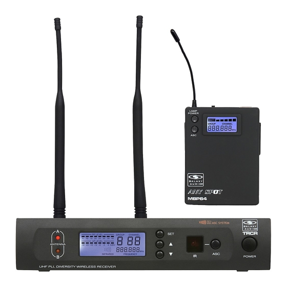
- Page 5 Antenna A LED. UP button of the System Menu. When lit, Antenna A is active. Please See“system setup”on page 7. Antenna B LED. IR window. When lit, Channel B antenna is active. This window sends an infrared signal to the transmitter for frequency synchronization.
-
Page 6: Changing Batteries
Condensor mic Dynamic mic LCD screen Please See “system setup ” on page 7. Power Switch Microphone Input Sensitivity Control. Left turn for output level decrease, right turn for output level increase. IR port Receivers infrared beam to synchronize frequencies. Changing Batteries: Batteries should be replaced when LCD indicator flashes. -
Page 7: Battery Replacement
Antenna. Gain Switch. There are three Gain settings on the MBP64. Select the setting most suitable to your application. Mic: Microphone Level 0: Guitar Level -10dB: Line Level Low Voltage/IR Transmission LED. LED On: Battery Voltage OK. LED Off: the Battery Voltage is Low. Flashing LED: IR transmission is in progress 3-pin Input Jack. -
Page 8: Transmitter Status Indications
TRC Receiver Setup: Frequency Group No. and Channel No. selection: ” ” key, and “GROUP Press“SET will flash. Press key to select suitable frequency group number, as shown in Diagram on the left. Then ” ” key, and “CHANNEL press“SET flashes. - Page 9 Included Single Rack Ears Two TNC connecting cables (optional) Two TNC connectors (optional) Optional Rack Shelf for mounting two Receivers side by side. MRTD/P/T...
-
Page 10: Tips For Improving System Performance
Maintain a line of sight between transmitter and antenna. Tips for improving System Performance Avoid placing the receiver near metal surfaces or any digital equipment (CD players, computers, etc) Keep the receiver away from the wall and at least 1m from the ground. Cellular telephones and two-way radios can interfere with the operation of wireless systems. -
Page 11: Handheld Transmitter
System Handheld Transmitter: Frequency Range: Code D 584 - 607MHZ Code L 655 - 679 MHZ Max Audio input level: 0dBV Transmitter Output level 10 dBm Band: UHF Dimensions: 9.6" x 2" dia. (243mm x 50mm dia.) Operating Range Under Typical Conditions: 300' Weight: 10.6oz (300 g) (without batteries) Note: actual range depends on RF signal... - Page 12 A limited ONE YEAR Warranty applies to the following products: 1. CHECKMATE Series-including CM130, CM140, CM150, CM160, CM-C200 and accessories 2. ANY SPOT Series-including AS-1000(R)(T), 500 & 700 SERIES, TOUR GUIDE/TRANSLATOR SYSTEMS, WIRELESS CAMERA KIT 3. ANY SPOT Accessories & Components 4.
Need help?
Do you have a question about the ANY SPOT and is the answer not in the manual?
Questions and answers