
Subscribe to Our Youtube Channel
Related Manuals for AMT Datasouth 4600


Summary of Contents for AMT Datasouth 4600
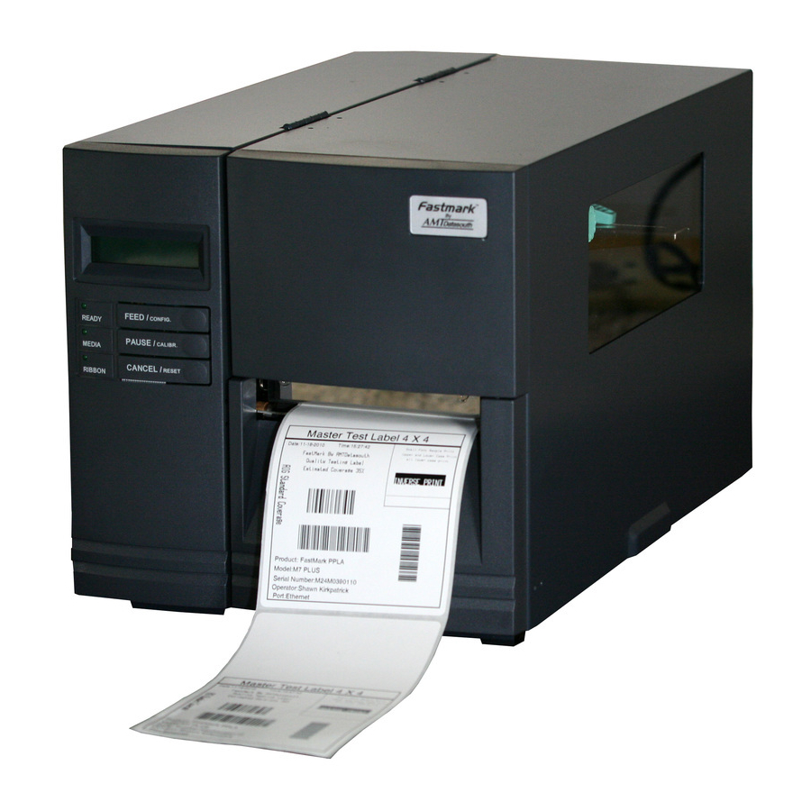
- Page 1 Fastmark 4600 PLUS Series Thermal Transfer Barcode Printer User’s Guide Document #140106A March 2011...
-
Page 2: Table Of Contents
Getting Started ... 2 Unpacking ... 2 Package Contents ... 3 Placing the Printer ... 4 Connecting the Power Cord ... 4 Getting to Know Your Printer ... 5 Front Panel ... 5 Loading a Ribbon ... 15 Loading Media ... 18 Print and Program Overview ... - Page 3 Appendix A: Printer Status ... 64 Appendix B: Stand-alone Keyboard and Barcode Reader ... 65 Keyboard ... 65 Form Control Functions ... 65 Barcode Reader ... 69 Appendix C: Cutter Installation ... 72 Appendix D: Dispenser Installation ... 75 Appendix E: Adjusting Ribbon Tension ... 78 Appendix F: Switching Ribbon Wound Ink-side out or Ink-side in...
- Page 4 Do not attempt to disassemble this printer if it malfunctions. All rights are reserved. No part of this document may be reproduced or issued to third parties in any form without permission of AMT Datasouth. The material in this document is provided for general information and is subject to change without notice.
-
Page 5: Getting Started
Getting Started Congratulations on choosing the AMT Datasouth Fastmark 4600 PLUS Series industrial barcode printer. This user‟s manual describing the FM 4600 PLUS Series printer models will help you get to know your new printer. The manual includes a guide to operate the printer as well as related information on troubleshooting, maintenance, and technical reference. -
Page 6: Package Contents
Package Contents 1. 4600 PLUS Series Printer 2. Installation Quick Start Guide 3. CD Rom (User Guides, Utility Software & Drivers) 4. AC Power Cord 5. Sample Ribbon... -
Page 7: Placing The Printer
Placing the Printer Before setting up and connecting the printer you should consider the following. WARNING! Do not operate the printer in an area where it might get wet. Find a solid flat surface with adequate room for the printer and enough space above for media and ribbon access. -
Page 8: Getting To Know Your Printer
Getting to Know Your Printer The illustrations below describe parts and features of the FM 4600 PLUS Series printer. Front Panel LCD Message Display Control Panel LED‟s and Switches Top Access Door Front Access Door The front panel includes: 3 LED indicators (READY, MEDIA and RIBBON) ... - Page 9 LED Indicators There are three LED indicators on the front panel, READY, MEDIA and RIBBON. These indicators display the operation status of the printer. On – Normal operation READY Off – Printer error On – Normal operation MEDIA Blinking – Install new media Printhead overheat The printer is paused, On –...
- Page 10 4. After self-test, the printer is in dump mode. For normal operation, you must press CANCEL to restart the printer. LCD Display The FM 4600 PLUS Series models have a LCD that shows: printer status printer settings input data from a keyboard or barcode reader The first parameter is either 203 or 300, which stands for the print resolution.
- Page 11 FM 4603 PLUS Series (300,PAL/PPLZ) <ESC> FOR KEYBD If a barcode reader is connected, the display shows: FM 4602 PLUS Series (203,PAL/PPLZ) WITH B.C. READER FM 4603 PLUS Series (300,PAL/PPLZ) WITH B.C. READER If an abnormal condition occurs, a related message is displayed. For example: RIBBON OUT Setting Display Language The printer‟s LCD display supports six languages: English, French, German,...
- Page 12 Changing Settings from the Panel You may change settings using the front panel buttons of the 4600 PLUS series printer models. In addition you may also change settings via software Utility and data stream commands. Buttons FEED+PAUSE FEED+CANCEL CANCEL FEED+CANCEL...
- Page 13 Basic Printer Features and Parameter Settings , PPLA/PPLB. NOTE: Features can vary based on printer model. Do not change settings during printing or communication. Feature Parameter PRINT MODE Thermal transfer / Direct thermal AUTO Mode 1~4 CALIBRATE MODE CUT/PEEL -015 ~+.050 OFFSET TPH VERTICAL -.003~+.003”...
- Page 14 Feature Parameter PARITY NONE (RS232) EVEN LENGTH 8 DATA BITS (RS232) 7 DATA BITS CLEAR FLASH YES/NO DHCP ENABLE DISABLE IP ADDRESS ###.###.###.### SUBNET MASK ###.###.###.### DEFAULT ###.###.###.### GATEWAY ####.####.#### ADDRESS Printer Features and Parameter Settings, PAL/PPLZ Feature Parameter PRINT MODE Thermal transfer / Direct thermal AUTO...
- Page 15 Feature Parameter PEELER INSTALLED COUNTING DOWN MEDIA SENSOR TYPE BLACK BAR PRESENT .0~040” DISTANCE 0~30 DARKNESS TRIM -30~30 DARKNESS BAUD RATE 600 / 1200 / 2400/ (RS232) 4800 / 9600 / 19200 /NONE PARITY NONE (RS232) EVEN LENGTH 8 DATA BITS (RS232) 7 DATA BITS CLEAR FLASH YES/NO...
- Page 16 Internal Parts and Features Thermal Printhead Paper Drive Roller Ribbon Pick-up Spindle Ribbon Supply Spindle Media Supply Spindle Head Latch Paper Sensor Guide Rear Feed Slot...
- Page 17 Peeler Option Cutter Module...
-
Page 18: Loading Ribbon And Media
Loading Ribbon and Media This section describes how to load ribbon and media. Loading a Ribbon Note: This section can be referred to, when transfer thermal printing is used. The steps below are based on ribbon wound ink-side in as an example. 1. - Page 19 2. Turn the head latch counter-clockwise and open the bracket. (Figure 2) 3. Unwrap the ribbon and separate the ribbon roll from the bare core. Insert the ribbon roll onto the ribbon supply spindle. (Figure 3) Head Latch Bracket Ribbon Supply Spindle...
- Page 20 4. Lead the ribbon through the print head module. (Figure 4) 5. Attach the edge of the ribbon onto the bare core and wind it a bit onto the core. Make sure the coating side of the ribbon is face down. Bar Core 6.
-
Page 21: Loading Media
Loading Media The 4600 PLUS series printers offer three different loading modes: standard, peel-off, or with a cutter. Standard mode allows you to collect each label freely. Peel-off mode peels backing material away from the label as it prints. After ... - Page 22 2. Turn the head latch counter-clockwise and open the bracket. Remove the outside media guide. (Figure 7) Head Latch Outside Media Guide Bracket...
- Page 23 3. Lead the media through the print head module and under the paper sensor guide. (Figure 8) Print Head Module Paper Sensor Guide Module 4. Return the outside media guide, close the bracket, and hook the head latch. (Figure 9) Head Latch Bracket...
- Page 24 5. Close the top cover and the front access door and turn on the printer, or press the “FEED” button if the printer is already on. (Figure 10)
-
Page 25: Peel Off Mode
Peel Off Mode Follow steps 1 to 3 in “Loading the Media – Standard Mode” above. 1. From the leading end of the media roll remove enough labels to expose 6-inches of backing/liner. (Figure 11) Backing Paper Remove labels... - Page 26 Lead the media backing/liner through the print head module. Print Head Module 3. Push down the peel-off mechanism release lever and lead the media backing/liner under the peeler module. (Figure 13) Media Backing/Liner Dispenser Module Peel Lever Media Backing/liner (Figure 12)
- Page 27 4. Close the peeler module using the peel-off mechanism release lever. (Figure 14) 5. Close the top access door and turn on the printer or press the FEED button if the printer is already on. (Figure 15) Notes: The FEED button does not make the printer peel. For peeling to occur when the panel setting is properly enabled.
- Page 28 Cutting Mode Follow steps 1 to 3 in “Loading the Media – Standard Mode” above. 1. Insert the media into the print head module and under the paper sensor guide. (Figure 16) Cutter Module Print Head Module Paper Sensor Guide...
- Page 29 2. Return the outside media guide, close the bracket, and hook the head latch. (Figure 17) Head Latch Bracket 3. Close the top access door and turn on the printer or press the FEED button if the printer is already on. The printer will then feed the labels through the cutter automatically.
-
Page 30: Pal Tm Print And Program Overview
Print and Program Overview Printers featuring PAL Print and Program ability can be used in several ways in any given environment. This section describes 3 common ways this advanced capability is used. For help and assistance determining the best way to use this ability in your situation, please consult your sales representative. -
Page 31: Standalone/Downtime Applications
Using a PAL Print and Program capable printer solves this problem. In this case a PAL program is written which interprets a data stream normally sent to the legacy device being replaced. This program is stored on the printer and is automatically executed each time the printer is powered on. - Page 32 The Standalone Application program is stored in the printer memory and can accept input from a PS/2 keyboard, bar code scanner, or other serial devices such as an electronic scale. These programs may use the printer‟s LCD to prompt for user input and may also include databases. Unlike other bar code printers that allow basic static forms to be loaded in the printer, PAL Program capable printers provide advanced abilities.
-
Page 33: Calibration & Configuration
Calibration & Configuration This section discusses calibration, printing configuration and resetting the printer to factory defaults. Performing Calibration After the media is loaded, please perform media calibration to calibrate the label sensor in advance. 1. Turn off the printer 2. Press and hold the PAUSE button and turn on the power. 3. -
Page 34: Printing A Configuration Report
Printing a Configuration Report To perform a self-test and print a configuration report: 1. Turn off the printer. 2. Press and hold the FEED button while turning on the power. 3. When “SELF-TESTING …” is displayed on the LCD and the READY indicator blinks, release the FEED button. -
Page 35: Resetting To Factory Default Settings
Resetting to Factory Default Settings To reset the printer to factory default settings: 1. Turn off the printer. 2. Press and hold the CANCEL button and turn on the printer. 3. When “E2PROM RESET …” is displayed on the LCD and the READY indicator blinks, release the CANCEL button. -
Page 36: Computer Connections
Computer Connections This printer comes with USB interface, a standard Centronics parallel interface, and a nine-pin Electronics Industries Association (EIA) RS-232 serial data interface. USB Interface Requirements The Universal Serial Bus (USB) interface is version 2.0 and 1.1 compliant and provides a full-speed (12Mb/s) interface that is compatible with your existing PC hardware. -
Page 37: Serial (Rs-232) Port
Serial (RS-232) Port The required cable must have a nine-pin "D" type male connector on one end, which is plugged into the mating serial port located on the back of the printer. The other end of the cable connects to a serial port on the host computer. For technical and pin-out information, please refer to the Technical Reference in this manual. -
Page 38: Ethernet Module Status Indicators
Ethernet Module Status Indicators LED Status Both Off No Ethernet link detected. The printer waits for printer ready. Blinking It will take about 20 seconds to be ready. Speed LED Green Amber Link/Activity LED Centronics Parallel Port USB Port RS232 Serial Port Description On: 100 Mbps link Off: 10 Mbps link... - Page 39 Ethernet LED Indicators Green LED Amber LED...
-
Page 40: Communicating With The Printer
Communicating with the Printer The bundled printer driver can be applied to all applications under Windows 2000/ 2003/ XP/ Vista/ Windows 7, supporting 32-bit/ 64-bit operation systems. With this driver you can operate any popular Windows software applications including Bartender editing software or MS Word, etc., to print to this printer. The screens included for these steps are taken from Windows XP;... - Page 41 1. Turn off the printer. Plug the power cable into the power socket on the wall, and then connect the other end of the cable to printer's power socket. Connect an interface cable (i.e USB, Parallel or Serial) from the printer to the 2.
- Page 42 5. Assign the directory to keep Seagull driver, (for example: C:\Seagull) and click "Next". 6. Click "Finish".
- Page 43 7. Select Install printer drivers and Click "Next" 8. Select model & emulation : TIA-230 TIA-230E TIZ-230...
- Page 44 9. Select the port of the printer and click "Next". 10. Enter Printer name and select "do not share this printer”, and click "Next". Argox X-3200 PPLB...
- Page 45 11. Check all the data on the showing screen, if it is correct, click "Finish". 12. After the related files have been copied to your system, click "Finish". Not Shared TIA-230E 7.1.8_M-0...
- Page 46 13. After driver installation is complete, click "Close". The driver should now be installed. Installed printer TIA-230E PPLB...
-
Page 47: Troubleshooting
Troubleshooting Normally, if the printer is in not working properly, the "READY" LED blinks continuously, and printing and communication between the host and printer stops. LED and LCD Diagnosis Blinking LEDs indicate a problem. Check the LEDs and the LCD display and refer to the following solutions: Media Problems LED/LCD... -
Page 48: Ribbon Problems
Ribbon Problems LED/LCD READY and RIBBON LEDs LCD Display Possible Problems Ribbon out Supply the ribbon roll Ribbon jam Recover the jam Ribbon sensor Replace ribbon sensor error Note: If you use direct thermal, set with panel, Windows driver or command. Other Problems READY LED Problems... -
Page 49: Light /Missing Print
Light /Missing Print Print quality can be adjusted when light or missing print is primarily observed on the right or left side of the media. Figure 1 Light/Missing Print If the print discrepancy is as shown in Fig. 1, turn the Fine Adjustment Knob clockwise one setting (adjust counter clockwise for Fig. -
Page 50: Miscellaneous
Miscellaneous If the host shows "Printer Time out" 1. Check if the communication cable (parallel or serial) is connected securely to your parallel or serial port on the PC and to the connector on the printer at the other end. 2. -
Page 51: Recovery
For unstable ribbon roll rotation, check the label path and make sure the head latch is securely closed. Poor printout quality: The ribbon may not be qualified. The media may not be qualified. Adjust the Darkness (heat temperature). Slow down the print speed. -
Page 52: Caring For Your Printer
Caring for Your Printer Clean the following components of the printer using a cotton bud dampened with alcohol. Do not soak the cotton bud excessively. Note: Turn off the printer before cleaning. Cleaning the Print Head Clean the print head as follows 1. -
Page 53: Cleaning The Roller
Cleaning the Roller Using a cotton bud moistened with alcohol, clean the roll and remove any attached glue. Note: Clean the roller after it has been in contact with foreign materials such as dust or adhesives. Cleaning the Media Compartment Clean the media compartment with a cotton bud that has been moistened with a mild detergent. -
Page 54: Technical Reference
Technical Reference General Specifications FM4602 PLUS Printing Method Printing Resolution Printing Width Printing Length Printing Speed 8MB DRAM (7MB User Available) Memory 4MB Flash ROM (3MB User Available) CPU Type Media Sensors Direct Thermal and Thermal Transfer 203 dpi (8 dots/.04”) Max 4.09”... - Page 55 LED indicator x 3, indicator Display Back-lit LCD Display 16 x 2-line, Multilingual Centronics parallel, Centronic s parallel, RS-232 serial, Communi cation RS-232 USB, interfaces serial, PS/2 keyboard Ethernet (4602 IE / 4603 IE) Maximum 8”(203mm) OD on a 3”(76mm) ID core Label 7”(178mm) OD on a 1.5”(38mm) ID core Roll...
- Page 56 Agency Listing Operating Temperatur Storage Temperatur Driver Operating Win 2000/ 2003/ XP/ Vista/ Windows 7 Systems Printer Languages Real Time Clock optional (RTC) Cutter Dispenser Rewinder Media Stacker Options and Standalone KDU: Accessories ArgoKee Font card CE, UL, CUL, FCC class A 40F~100F (4C~38C) -4F~122F (-20C~50C) PPLA,...
-
Page 57: Fonts, Bar Codes And Graphics Specification
EAN-8, EAN-13,UPC-A, UPC-E, Postnet, Codabar, Code 128 subset A/B/C, UCC/EAN-128, UCC/EAN-128 K-MART, UCC/EAN-128 Random Weight, Plessey, HBIC, Telepen, FIM, UPC2, UPC5, GS1 Data Bar Graphics PCX, BMP, IMG, and HEX formats Stand-alone Operation 4600 PLUS Series ArgoKee... - Page 58 Interleave 2 of 5(checksum), Matrix 25, UPC A/E 2 and 5 add-on, EAN-8/13, Code 128UCC, UCC/EAN, Postnet, German Postcode. MaxiCode and PDF417 (2D symbologies) Graphics PCX and binary raster Stand-alone connect with PC keyboard or barcode Operation reader (PS/2 interface) 4600 PLUS Series...
- Page 59 , Code 39, Code 128 (A, B&C), Codabar, Logmars, MSI, UPC/EAN extension EAN-8, EAN-13, UPC-A, UPC-E and PostNet Two-Dimension barcode: PDF-417, MaxiCode, Data Matrix (ECC200 only), QR Code Graphics HEX and binary graphics with normal as well as compressed image 4600 PLUS Series...
-
Page 60: Interface Specifications
Interface Specifications This section presents the interface specifications of IO ports for the printer. These include pin assignments, protocols and detailed information about how to properly interface your printer with your host or terminal. USB series “B” Receptacle Interface Signal Name VBUS Connector Terminal Pin Assignment... - Page 61 Serial Interface The RS-232 connector on the printer side is a female, DB-9. Direction Definition RxData TxData Ground Note: Pin 9 is reserved for a KDU (keyboard device unit). Do not connect this pin if you use a general host such as a PC...
- Page 62 Connection with Host: Host 25S Printer 9P Host 9S (PC or compatible) (PC or compatible) DTR 20 …… 1 DSR DTR 4 DSR 6 …… 6 DTR DSR 6 …… 2 RX TX 2 TX 3 …… 3 TX RX 3 RX 2 CTS 5 ……...
- Page 63 The simplest way to connect to other hosts (not PC compatible) or terminals is: Printer Pin 2- RxData ……… Pin 3- TxData ……… Pin 5- Ground ……… In general, as long as the data quantity is not too large and you use Xon/Xoff as flow control, it will be problem free.
- Page 64 Parallel (Centronics) The parallel port is a standard 36-pin Centronics connector. Pin assignments are as follows: Pin Direction Definition /STROBE Data1 Data 2 Data3 Data4 Data5 Data6 Data7 Data8 /ACK BUSY Auto Polling Both the serial port and parallel port of this printer can be active at the same time, i.e.
- Page 65 Ethernet Interface The following port complies with Ethernet communication. Signal Transmit+ Transmit- Receive+ Reserved Reserved Receive- Reserved Reserved...
-
Page 66: Ascii Table
ASCII TABLE " XOFF & ‛ < >... -
Page 67: Appendix A: Printer Status
Appendix A: Printer Status LCD display Blinking LED PAUSE READY MEDIA OUT MEDIA READY RIBBON OUT RIBBON READY SERIAL IO READY ERROR CUTTER READY FAILED MEMORY FULL READY HEAD OPEN READY P. SENSOR READY O.R. TPH TOO HOT MEDIA Description Printer is paused. -
Page 68: Appendix B: Stand-Alone Keyboard And Barcode Reader
Appendix B: Stand-alone Keyboard and Barcode Reader This appendix covers stand-alone operation with keyboard or barcode reader. Keyboard To use the printer in stand-alone operation with a keyboard follow the procedure described below: 1. Make a form for the keyboard. (The form should include “ZS” command to store to flash memory. - Page 69 Example: Making a Keyboard Form 1. Make a command file for the form, KBD.FRM. Command FK"KBDFORM" FS"KBDFORM" V00,15,N,"Product Name ?" C0,10,N,+1,"Product No. ?" Q50,24 q816 A550,20,0,4,1,1,R,"ABC COMPANY" B550,60,0,2,2,4,40,B,C0 A540,150,0,3,1,1,N,V00 2. Send the file, KBD.FRM to printer under MS-DOS >COPY/B KBD.FRM LPT1: Description Enable store to flash Delete previous one...
- Page 70 3. Turn off the printer, connect the keyboard and then turn on the printer. The LCD displays this message: READY (203,PPLB) <ESC> FOR KEYBD 4. Press <ESC> to enter the keyboard mode and the form name appears. Press <ENTER> to select the form. KBDFORM ...
- Page 71 7. Press <ENTER> to continue to the next label and repeat steps 5 ~ 7, or <ESC> to exit. ENTER to go on, Or ESC to return Output...
-
Page 72: Barcode Reader
Barcode Reader To use the printer in stand-alone operation with a barcode reader (scanner), follow the procedure described below 1. Make a form for barcode reader. (Note that the form name must be “READER” The form should include “ZS” command to store to flash memory.) 2. - Page 73 Example: Making a Barcode Reader Form 1. Make a command file for a form, READER.FRM. Command FK"READER" FS"READER" V00,15,N,"Product Name ?" C0,10,N,+1,"Product No. ?" Q50,24 q816 A550,20,0,4,1,1,R,"ABC COMPANY" B550,60,0,2,2,4,40,B,C0 A540,150,0,3,1,1,N,V00 2. Send the file READER.FRM to printer under MS-DOS >COPY/B READER.FRM LPT1: 3.
- Page 74 4. The form READER is automatically executed. Scan product name and number from printed bar codes using the barcode reader. Product No.? 11223344 Product Name? APPLE 5. A label is printed. The copy count depends on the PA command for the READER form.
-
Page 75: Appendix C: Cutter Installation
Appendix C: Cutter Installation Refer to the following steps to install the cutter kit onto printers: 1. Turn off the printer. 2. Remove the top covers on both left and right sides. 3. Install the Cutter Baby Board to the main board JP17 socket of 4602 PLUS series / JP15 socket of 4603 PLUS series. - Page 76 (CUTTER) on the 4602 PLUS series main boards, or to the JP14 connector (CUTTER) on the main board of 4603 PLUS series. 8. Turn on the printer. 9. For the 4600 PLUS series models, set the parameter of “CUTTER INSTALLED” on the LCD to the ON position.
- Page 77 After the cutter is installed, install media and ribbon. 1. Put the media end on the roller. 2. Close the TPH latch. 3. Hold the PAUSE button and turn on the printer. 4. Release the button when the cutter starts cutting. 5.
-
Page 78: Appendix D: Dispenser Installation
Appendix D: Dispenser Installation Install a dispenser into the printer as follows: 1. Turn off the printer. 2. Remove the top cover on both left and right sides. 3. Assemble the related components for both left and right sides. Check below:... - Page 79 4. Connect the Peeler sensor to main board JP15 socket of 4602 PLUS series/ JP12 socket of 4603 PLUS series. Secure the dispenser board onto printer case. 5. Insert the left side of dispenser bracket and secure the three screws to the TPH module.
- Page 80 6. Install the ribbon and media. 7. Turn on the printer. 8. For the 4600 PLUS series models, set the parameter of “DISPENSER INSTALLED” on the LCD to the ON position.
-
Page 81: Appendix E: Adjusting Ribbon Tension
Appendix E: Adjusting Ribbon Tension The ribbon shaft has its user-friendly feature to allow users to adjust the tension of ribbon shaft by rotating the knob. User can reset to factory default tension by adjusting the ribbon shaft while the black line was aligned to the marked arrows. Appendix F: Switching Ribbon Wound Ink-side out or Ink-side in The printer is produced to suit flexible applications, no matter with ribbon wound ink-side in (manufacturing default), or with ribbon wound ink-side out. - Page 82 2. After the adjustment, ribbon wound ink-side in can be use. Then install the ribbon: 3. If ribbon wound ink-side out is in use, pull and move the SHAFT RIBBON ADJ into the Outside. Then install the ribbon:...
Need help?
Do you have a question about the 4600 and is the answer not in the manual?
Questions and answers