Sign In
Upload
Download
Table of Contents
Contents
Add to my manuals
Delete from my manuals
Share
URL of this page:
HTML Link:
Bookmark this page
Add
Manual will be automatically added to "My Manuals"
Print this page
×
Bookmark added
×
Added to my manuals
Manuals
Brands
Clear-Com Manuals
Intercom System
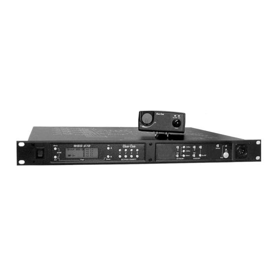
WBS-670
Operating instructions manual
Clear-Com WBS-670 Operating Instructions Manual
Professional wireless intercom system
Hide thumbs
1
2
Table Of Contents
3
4
5
6
7
8
9
10
11
12
13
14
15
16
17
18
19
20
21
22
23
24
25
26
27
28
29
30
31
32
33
34
35
36
37
38
39
40
41
42
43
44
45
46
47
48
49
50
51
52
53
54
55
56
57
58
59
60
61
62
page
of
62
Go
/
62
Contents
Table of Contents
Troubleshooting
Bookmarks
Table of Contents
Operating Instructions
Table of Contents
Introduction
General Description
System Features
WBS-670 Base Station
Controls and Connections - Front Panel
Controls and Connections - Rear Panel
WBS-670 Specifications
WTR-670 Beltpack
Controls and Connections - Top Panel
Controls and Connections - Rear Panel
WTR-670 Specifications
Initial Equipment Set-Up
Unpacking
Antenna Connections
Antenna Polarization
Distance between Antennas
Antenna Placement
Improving Reception/Increasing Range
Base Station Set-Up
Location
Power Connection
Transmit Switches
Intercom Switch
Intercom Interface
Auxiliary Input/Output
Beltpack Set-Up
Battery Installation
Antenna Connection
Transmit Mode
Headset Connection
Pre-Walk-Thru Checklist
System Operation
Frequency Plan Overview
Factory-Defined Groups
User-Programmable Groups
System Quick Start
Base Station Operation
Power
Local Headset
Beltpack Connect
Intercom
Auxiliary
Display Contrast
WBS-670 Menu Structure
Main Screen Flowchart
Operating Screen
Power-Up Screen
Beltpack Activity Code Definitions
Group/Channel Select
Group/Frequency Select
Frequency Edit
Scan
1St Use Default
Copy
Factory Default
Lockout
Special Key Sequences
Beltpack Operation
Power/Local Headset Volume
Battery Check
Talk Button
Microphone Gain
Beltpack Menu Structure
Group/Channel Screen
Power-Up Screens
Receive Screen
Transmit Screen
Scan
1St Use Default
Factory Default
Lockout
Special Key Sequences
Talk Button Latch On/Latch off
System Walk-Thru
Troubleshooting
Tech Tips
Frequency Interaction
Microphone Gain Adjustment
Battery Information
Accessories and Replacement Parts
Customer Service Information
Certification Information
Clear-Com Limited Warranty
Advertisement
Quick Links
1
Operating Instructions
2
Wbs-670 Base Station
3
Controls and Connections - Rear Panel
4
Wtr-670 Beltpack
5
Frequency Plan Overview
Download this manual
Operating Instructions
WBS-670, WTR-670
Professional
Wireless
Intercom System
R
Intercom Systems
Table of
Contents
Previous
Page
Next
Page
1
2
3
4
5
Advertisement
Table of Contents
Need help?
Do you have a question about the WBS-670 and is the answer not in the manual?
Ask a question
Questions and answers
Related Manuals for Clear-Com WBS-670
Intercom System Clear-Com WTR-670 Operating Instructions Manual
Professional wireless intercom system (62 pages)
Intercom System Clear-Com WBS-680 Operating Instructions Manual
Professional wireless intercom system (86 pages)
Intercom System Clear-Com WTR-680 Operating Instructions Manual
Professional wireless intercom system (86 pages)
Intercom System Clear-Com WBS Operating Instructions Manual
Wireless intercom system (15 pages)
Intercom System Clear-Com WBS Operating Instructions Manual
Wireless intercom system (13 pages)
Intercom System Clear-Com HME DX410 User Manual
Dual-channel wireless intercom (38 pages)
Intercom System Clear-Com FreeSpeak II User Manual
Base station system wireless intercom system (106 pages)
Intercom System Clear-Com Eclipse HX User Manual
(259 pages)
Intercom System Clear-Com ICS-102 Instruction Manual
Intercom panel (81 pages)
Intercom System Clear-Com HME DX210 Operating Instructions Manual
Dual-channel wireless intercom (43 pages)
Intercom System Clear-Com HMS-4X Technical Manual
Ip network guidance: helixnet digital partyline (22 pages)
Intercom System Clear-Com FreeSpeak II User Manual
(143 pages)
Intercom System Clear-Com Eclipse HX-Delta User Manual
(193 pages)
Intercom System Clear-Com FreeSpeak II FSII-TCVR-24 User Manual
For eclipse hx (102 pages)
Intercom System Clear-Com TEMPEST 2400 Reference Manual
Wireless intercom system (100 pages)
Intercom System Clear-Com ENCORE MS-702 Instruction Manual
Two-channel main station (32 pages)
This manual is also suitable for:
Wtr-670
Table of Contents
Print
Rename the bookmark
Delete bookmark?
Delete from my manuals?
Login
Sign In
OR
Sign in with Facebook
Sign in with Google
Upload manual
Upload from disk
Upload from URL


Need help?
Do you have a question about the WBS-670 and is the answer not in the manual?
Questions and answers