
Subscribe to Our Youtube Channel
Related Manuals for Clear-Com ENCORE MS-702


Summary of Contents for Clear-Com ENCORE MS-702
- Page 1 CLEAR-COM ENCORE MS-702 TWO-CHANNEL MAIN STATION I N S T R U C T I O N M A N U A L...
- Page 2 Room 1806, Hua Bin Building No. 8 Yong An Dong Li Jian Guo Men Wai Ave Chao Yang District Beijing, P.R. China 100022 Clear-Com is a registered trademark of Vitec Group Communications. The Clear-Com Logo is a registered trademark of Vitec Group Communications.
-
Page 3: Table Of Contents
CONTENTS OPERATION ........1-1 Introduction . - Page 4 M S - 7 0 2 T W O - C H A N N E L M A I N S T A T I O N...
- Page 5 IMPORTANT SAFETY INSTRUCTIONS 1. Read these instructions. 2. Keep these instructions. 3. Heed all warnings. 4. Follow all instructions. 5. Do not use this apparatus near water. 6. Clean only with dry cloth. 7. Do not block any ventilation openings. Install in accordance with the manufacturer’s instructions.
- Page 6 CAUTION RISK OF ELECTRIC SHOCK DO NOT OPEN This symbol alerts you to the presence of uninsulated dangerous voltage within the product's enclosure that might be of sufficient magnitude to constitute a risk of electric shock. Do not open the product's case. This symbol informs you that important operating and main- tenance instructions are included in the literature accompanying this product.
-
Page 7: Operation
The MS-702 two-channel main station is a powerful, yet user-friendly unit that yet user-friendly unit that can serve as the heart of a Clear-Com system. We recommend that you read can serve as the heart of a through this manual completely to better understand the functions of the MS-702. -
Page 8: Operation
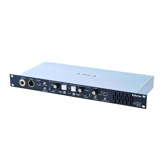
The MS-702 also incorporates a dual-channel program interrupt system (IFB). When activated, one or more stations can interrupt the program audio to either another intercom station or a talent wearing Clear-Com’s wired or wireless talent receivers. Clear-Com’s stand-alone IFB system can also be connected to this station. - Page 9 2-Channel Main Station MS-702 Figure 1-1: Front Panel 1. Talk Buttons: Each channel has an illuminated talk button for activating the microphone feed to that channel. Each talk button has a dual action (momentary or latching feature) depending on how the button is pressed. If desired, the latching function for each channel can be defeated using the option switches on the rear panel.
- Page 10 3. Tone Alert: An audible tone alert can be enabled to sound when a call signal is received on either channel. This can be useful when the operator's attention has been drawn away from the MS-702 indicator panel. Press the tone alert button to alternately enable or disable the audible tone alert.
- Page 11 • OFF: The channel will not receive program audio when the switch is set to off. • INTRPT: Pressing the talk button will interrupt the program when this switch is set to intrpt. Note: You can set this feature so that pressing the call button for a channel, rather than the talk button, interrupts the program audio.
- Page 12 This adjustment should only be carried out by qualified service personnel. 18. Panel Mic Connector: Clear-Com recommends the GM-9 and GM-18 plug-in panel microphones for use with the MS-702. The GM-9 is 9 in. (22.86 cm) long and the GM-18 is 18 in. (45.72 cm) long. The microphone is an electret type.
-
Page 13: Rear Panel
19. Headset Connector: The headset connector is located on the front panel. All Clear-Com headsets are recommended for use with the MS-702. The following is a description of the characteristics of a suitable headset: Mic Type --- Dynamic, see technical specifications for details... - Page 14 6. INTRPT EXT IFB: When the hot mic output is connected to Clear-Com’s IFB system and the interrupt external IFB switch is set to the on position, pressing a key on the IFB system will disconnect the selected headset or panel microphone from the intercom line(s).
- Page 15 17. Power Switch: The power switch can be used to turn AC power to the MS-702 on and off. When in the on position, the front-panel talk buttons illuminate blue. 20. AC Power Connection: An IEC type 320 connector is provided to interface to the appropriate AC power cord to be used.
- Page 16 It provides an output signal from the selected headset or panel microphone. This output is intended to interface with the external line-in jack on Clear-Com’s IFB System. The jack is wired as follows: Ring --- Ext. IFB control signal input...
-
Page 17: Re-Setting Program Interrupt Options
unit is shipped with the headset audio limiter on. You can turn this feature on or off by using a jumper located on the main circuit board. Note: This adjustment should only be carried out by qualified service personnel. To turn the audio limiter on or off: 1. - Page 18 • For channel B: The JP6 three-pin jumper, located in the center of the circuit board. 5. A jumper plug covers two of the three pins on each jumper. To change the program-interrupt option on your station, do one of the following: •...
-
Page 19: Installation
2. Connect the proper AC mains cable. 3. Install the MS-702. Note: For additional information, refer to the Clear-Com System Installation Manual. 4. Connect the AC to the mains circuit. Note: Information on the mains power requirement is given on the underside of the unit. - Page 20 2 - 2 M S - 7 0 2 T W O - C H A N N E L M A I N S T A T I O N...
-
Page 21: Maintenance
MAINTENANCE INTRODUCTION This chapter provides maintenance information, including a block diagram and troubleshooting tips. Caution:These servicing instructions are for use by qualified personnel only. To reduce the risk of electrical shock, do not perform any servicing other than that contained in the operating instructions unless you are qualified to do so. MS-702 BLOCK DIAGRAM The following is a block diagram of the MS-702: MS-702... -
Page 22: Troubleshooting Tips
TROUBLESHOOTING TIPS SYMPTOM CAUSE SOLUTION System does not operate. Blue No AC power to the MS-702. Make sure the power switch on the talk buttons do not illuminate rear panel is turned on. Check the AC and short lights do not connection and cable. - Page 23 Excessive DC loading of intercom Remove any audio transformers or line. other equipment that may be connected across the intercom line. If equipment other than Clear-Com intercom equipment must be connected to the intercom line, please contact Clear-Com application or service personnel for advice.
- Page 24 SYMPTOM CAUSE SOLUTION Far too many terminations on the Check all main stations and power intercom line. supplies to make sure each intercom channel is terminated at only one point. Table 3-1: Troubleshooting Tips 3 - 4 M S - 7 0 2 T W O - C H A N N E L M A I N S T A T I O N...
-
Page 25: Technical Specifications
TECHNICAL SPECIFICATIONS MS-702 TWO-CHANNEL STATION dBu is an absolute measurement. 0 dBu is referenced to 0.775 volts RMS Panel Microphone Input Input Type Electret Input Impedance >=2KΩ Mic Limiter Threshold 0 dBu ±3 dB Mic Limiter Range >= 20 dB Headset Microphone Input Input Type Dynamic... - Page 26 IFB/Hot Mic Type Unbalanced Output Impedance 180Ω Load Impedance >= 600Ω Frequency Response Panel Mic - Party Line 600 - 10KHz ± 3dB Headset Mic - Party Line 200 - 12KHz ± 3 dB Headset Mic - Line Out 200 - 12KHz ± 3 dB Program Input - Party Line 100 - 17KHz ±...
- Page 27 Mains Power Input Voltage Range 100 - 240 VAC Input Frequency Range 50 - 60 Hz Input Power <= 60 VAC Output Voltage 30 VDC ± 0.5V Output Current per Channel (Continuous) 1.2 A Output Current per Channel (Peak) 2 A (Do not exceed the 1.2A rating for more than 2 seconds per 1 minute period) Short Circuit Recovery Time (1st short)
- Page 28 Weight 6.06 lbs. (2.75 kg) Notice About Specifications While Clear-Com makes every attempt to maintain the accuracy of the information contained in its product manuals, that information is subject to change without notice. Performance specifications included in this manual are design-center specifications and are included for customer guidance and to facilitate system installation.
-
Page 29: Limited Warranty
• UHF wireless intercom systems have a limited warranty of three years. • All other Clear-Com and Drake brand systems and products, including beltpacks, have a limited warranty of two years. The warranty starts at the time of the product’s original purchase. The warranty... -
Page 30: Warranty Repairs And Returns
such agreement. For more information, contact your authorized dealer, distributor, or sales representative. Instructions for reaching VGC’s User Support Centers are given below. Telephone for Europe, Middle East and Africa: +49 40 6688 4040 Telephone for the Americas and Asia: +1 510 337 6600 Email: vitec.support@AVC.de Once the standard warranty period has expired, the User Support Center will continue to provide telephone support if you have purchased an Extended... -
Page 31: Service Contract
years the warranty of any product offered with a standard two-year warranty. The total warranty period will not extend beyond five years. Any purchase of an extended warranty provides 24 x 7 customer support in addition to the warranty immediately upon purchase of the warranty extension. Note: VGC does not offer warranty extensions on UHF wireless intercom systems, or on any product with a 1-year or 90-day warranty. - Page 32 of customer furnished components resulting in damage to VGC provided product. This limited warranty is not transferable and cannot be enforced by anyone other than the original consumer purchaser. This warranty gives you specific legal rights and you may have other rights which vary from country to country.
Need help?
Do you have a question about the ENCORE MS-702 and is the answer not in the manual?
Questions and answers