
Related Manuals for astra telematics AT240


Summary of Contents for astra telematics AT240
-
Page 1: User Guide
AT240 Advanced Vehicle Tracking Device User Guide Version: Date: December 2013... - Page 2 Abbreviations Analogue to Digital Converter ASCII American Standard Code for Information Interchange (computer character set) Bluetooth Low Energy Controller Area Network Direct Current Field Effect Transistor Geographic Information System GPRS General Packet Radio Service (part of GSM) Global Positioning System Global System for Mobile communication Internet Protocol (part of TCP/IP) Light Emitting Diode...
-
Page 3: Product Overview
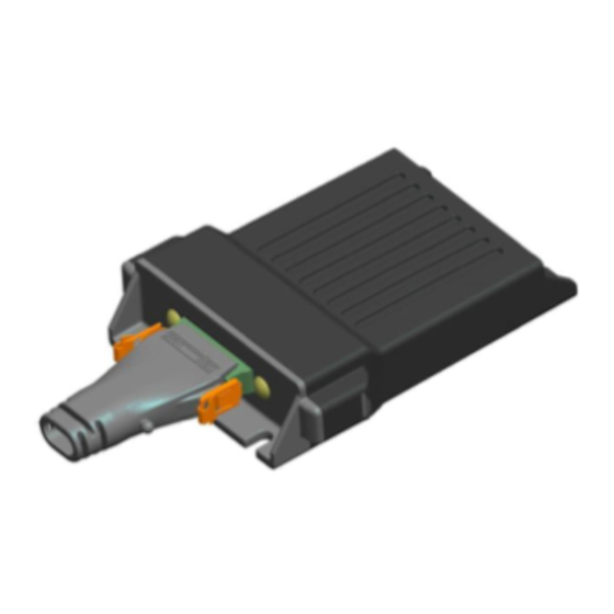
Product Overview The AT240 is a highly featured vehicle tracking device, housed in a sturdy plastic enclosure with internal GPS/GSM antennas and sealed to IP67 specifications. The AT240 incorporates the very latest technology, including the latest Cortex M3 ARM processor, Telit GE865 Quad Band GSM/GPRS modem and SiRFstar IV GPS with high sensitivity and anti-jamming features. -
Page 4: Technical Specifications
Technical Specifications E-GSM/GPRS Modem: 2 Watts (E-GSM900 and GSM850 Class 4) 1 Watt (GSM1800 and GSM1900 Class 1) GPRS multi-slot class 10 GSM up-link (TX): Frequencies 824 – 849 MHz, 880 – 915 MHz, 1710 - 1785 MHz, 1850 – 1910 MHz GSM down-link (RX): Frequencies 869 –... -
Page 5: Hardware Description
Hardware Description Overall Dimensions 104 x 85 x 24 mm SIM installation... - Page 6 The AT240 operates from a DC Voltage between 7 and 36 Volts. We recommend that a permanent ‘live’ power source is used to supply the AT240. If current drain is of concern, please refer to the power management section for options to minimise vehicle battery drain when stationary for long periods.
- Page 7 Digital inputs 5 and 6 are normally high, for use in pull-down applications. Simply switch to GND to activate these inputs. Note: damage may be caused to the AT240 device if a voltage source is applied to digital inputs 5 and 6.
- Page 8 ID Application Note for more details of how to use this feature. CANBus The AT240 has integrated CANBus. Please refer to CANBus and FMS Application Notes for details of supported protocols and features. IMPORTANT NOTE: The CANBus pins are ESD protected to 15kV, but can only withstand a continuous voltage of 12V maximum.
-
Page 9: Electrical Parameters
Electrical Parameters Operating Conditions Parameter Units Power Supply Input Voltage Digital Input High Voltage Threshold +5.0 Digital Input Low Voltage Threshold +2.0 Digital Maximum Voltage +30.0 Digital Maximum Current Absolute Maximum Ratings Parameter Units Power Supply Input Voltage Voltage on Digital 1-4 and ADC Inputs Voltage on Digital 5-6 (pull-down) +3.3 Voltage on RS232 RX... - Page 10 The AT240 has a versatile set of features to facilitate detailed customisation. Programming with an ASCII Terminal Custom configuration of the AT240 is best achieved via a serial interface to a PC. It is possible to use any ASCII terminal program (e.g. HyperTerminal, Teraterm, ProComm, Com7 etc.) to enter commands.
- Page 11 Multiple Command Format In SMS mode it is often convenient to send several commands together in one SMS or packet. It is possible to append multiple commands together as described below. Example1 $DIST,50<CRLF> $GPSQ,100<CRLF> Example2 (recommended format for TCP/UDP mode) $DIST,500$APPW,orangeinternet$FRED,1 Multiple Command Response Format Multiple commands received at the same time via any mode will result in one response for each...
-
Page 12: Application Parameters
See above. TCP Acknowledgment Timeout (TCPT) This parameter specifies the maximum number of seconds that the AT240 device will wait for the host to send the ACK code in response to sending a report. The default value is 30 seconds. A value of zero will disable the acknowledgment feature. - Page 13 SMS Monthly Usage Limit (SMSL) This parameter can be used to control SMS costs by setting a monthly limit on the number of SMS which may be sent from the AT240. A value of zero will disable the Monthly SMS Limit feature.
- Page 14 IDLE is 180 seconds. Over-speed Speed Threshold (OSST) The AT240 can be configured to report over-speed events, which are defined as exceeding a given speed for a given amount of time. The OSST parameter defines the over-speed threshold in kmh.
- Page 15 IGNM mode 3. STOP Report Delay (STPD) When IGNM is set to zero (see above), the AT240 will determine journey START and STOP events from GPS. A STOP event will occur after the vehicle has remained stationary for a pre- determined time.
- Page 16 For use in iButton modes 2 and 3 In these modes, ibutton must be presented before the vehicle engine is started. If no ibutton was seen for auth_timeout_secs the AT240 output switch will be closed to activate the reminder (buzzer or indicator light etc.) <imob_output_state>...
- Page 17 Debug Level (DBUG) Set the level of debug information displayed in the NMEA serial output as defined in the following table. DBUG level Information displayed Only NMEA output on serial port 1 Display errors only Display normal diagnostic information Display extended diagnostic information Display maximum diagnostic information OTA Programming PIN Code (PASS) OTA PIN code feature, which can be used to prevent unauthorised reconfiguration by SMS.
- Page 18 COLN specifies the threshold in m/s/s * 10, integer format. Device Orientation (ORTN) This parameter defines the AT240 installation orientation in order to allow corrections to be applied to the accelerometer X/Y data to ensure data is correctly orientated with the vehicle axis.
- Page 19 Tow Alert Parameters (TOWP) A tow alert (i.e. report with REASON bit set indicating tow alert event) is generated whenever movement is detected whilst the vehicle ignition is off. This scenario is detected using a number of different sources, including GPS speed, GPS location and accelerometer based motion sensor. The sensitivity of tow alert detection can be changed by editing the various decision thresholds using the TOWP command.
- Page 20 Utility and Engineering Commands Delete All Geofences (GEOD) Individual geofences can be deleted by setting <type> to zero. The GEOD command provides a convenient way of deleting all geofences. Configure Digital Outputs (CDIG) Where an output is controlled in response to an event the digital output used can be configured using this command.
- Page 21 <mode> IMOB Conditions Clear immobilisation mode and deactivate output switch (OFF) Activate output switch when vehicle ignition is OFF Activate output switch when vehicle is stationary Activate output switch when vehicle is stationary AND ignition is OFF (DEFAULT) Activate output switch immediately and unconditionally Automatic Immobilisation Schedule Settings (IMOS) Automatic immobilisation can be scheduled individually for each day of the week using this command.
- Page 22 Resets all parameters to factory defaults (or client defaults) as built into the device firmware. Position on Demand (POLL) The AT240 will send an update report to the host server in response to a variety of user- configurable events. The POLL command can be used to request an update when there is no...
- Page 23 Firmware Update (LOAD) AT240 firmware can be updated over GPRS with this command. The firmware files must first be loaded onto a webserver in the correct format. Please contact Astra Telematics for support and assistance on remote firmware updates. $LOAD,<host-ip-address>,<port-number>,<pathname>,<filename><CR><LF>...
- Page 24 NMEA sentences and zero disables all NMEA GPS output (see DBUG to enable/disable other serial output). Serial Port Baud Rate (BAUD) Configure the baud rate of the AT240 RS232 serial port Display Settings (SHOW) Display settings in readable ASCII format (not recommended for TCP/SMS, see PARA) Send SMS (SSMS) Send an SMS text message.
-
Page 25: Error Codes
Status Check (STAT) – Response Format STATUS: Fixed packet header AT240 serial number 15 digit IMEI number (serial number of device) Software version number Floating point number Date of the last GPS fix dd/mm/yy Time of the last GPS fix... - Page 26 Parameter Check (PARA) – Response Format PARA: Fixed packet header Software version number Floating point number SERV SMS host number International format telephone IPAD primary TCP IP address TCP IP address PORT primary TCP port number TCP port number - integer IPAD2 TCP IP address for PTDM mode TCP IP address PORT2 TCP port number for PTDM mode...
Need help?
Do you have a question about the AT240 and is the answer not in the manual?
Questions and answers