astra telematics AT210 User Manual
Vehicle tracking device
Hide thumbs
Also See for AT210:
- User manual (29 pages) ,
- Installation manual (5 pages) ,
- Quick start manual (4 pages)

Related Manuals for astra telematics AT210


Summary of Contents for astra telematics AT210
-
Page 1: User Guide
AT210 Vehicle Tracking Device Version 5.x Hardware User Guide Document Version: Device Version: 5.0+ Date: July 2017... - Page 2 Abbreviations Analogue to Digital Converter ASCII American Standard Code for Information Interchange (computer character set) Bluetooth Low Energy Controller Area Network Direct Current Field Effect Transistor Geographic Information System GNSS Global Navigation Satellite System GPRS General Packet Radio Service (part of GSM) GNSS Global Positioning System Global System for Mobile communication...
-
Page 3: Product Overview
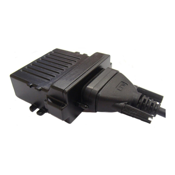
Product Overview The AT210 is simple vehicle tracking device, housed in a sturdy plastic enclosure, sealed to IP67 specifications and designed for plant & machinery applications. Both GNSS and GSM antennas are internal, with the option to use an external GNSS antenna when the device cannot be mounted in a location with good sky visibility. -
Page 4: Technical Specifications
Technical Specifications E-GSM/GPRS Modem: 2 Watts (E-GSM900 and GSM850 Class 4) 1 Watt (GSM1800 and GSM1900 Class 1) GPRS multi-slot class 10 GSM up-link (TX): Frequencies 824 – 849 MHz, 880 – 915 MHz, 1710 - 1785 MHz, 1850 – 1910 MHz GSM down-link (RX): Frequencies 869 –... -
Page 5: Hardware Description
Hardware Description Overall Dimensions 77 x 71 x 32 mm Back-up battery Each AT210 is supplied with a 510mAh back-up battery, which is fixed to the PCB and connected as shown below:... - Page 6 For a full table of AT210 connections please see page 8. Power requirements The AT210 operates from a DC Voltage between 6 and 36 Volts. We recommend that a permanent ‘live’ power source is used to supply the AT210. If current drain is of concern, please see the power-down option of the $IGNM command, which can be used to minimise battery drain when vehicles may be stationary for long periods.
- Page 7 Status LEDs The AT210 has internal status LEDs as below: GNSS status GSM Network registration status External power During normal operation the LEDs should appear as below: GNSS double flash once per second single flash every 2 seconds POWER stays on constantly...
- Page 8 1A in-line fuse with these switches is essential to prevent any damage through fault scenarios. Integrated Accelerometer The AT210 has a built in 3 axis MEMS accelerometer that operates in the range ±2g and is used to measure driver behaviour (acceleration and braking) during normal driving conditions.
-
Page 9: Electrical Parameters
Electrical Parameters Operating Conditions Parameter Units Power Supply Input Voltage Digital Input High Voltage Threshold +5.0 Digital Input Low Voltage Threshold +2.0 Digital Maximum Voltage +30.0 Digital Maximum Current Absolute Maximum Ratings Parameter Units Power Supply Input Voltage Voltage on RS232 RX Voltage on RS232 TX Voltage on iButton/Dallas Interface Current sunk by MOSFET low side switches...
Need help?
Do you have a question about the AT210 and is the answer not in the manual?
Questions and answers