
Subscribe to Our Youtube Channel
Related Manuals for astra telematics AT110V5


Summary of Contents for astra telematics AT110V5
-
Page 1: User Guide
AT110V5 Advanced Vehicle Tracking Device User Guide Version: Date: September 2018... - Page 2 Abbreviations Analogue to Digital Converter ASCII American Standard Code for Information Interchange (computer character set) Bluetooth Low Energy Bluetooth (Classic) Controller Area Network Direct Current Field Effect Transistor Geographic Information System GPRS General Packet Radio Service (part of GSM) Global Positioning System GNSS Global Navigation Satellite System Global System for Mobile communication...
-
Page 3: Product Overview
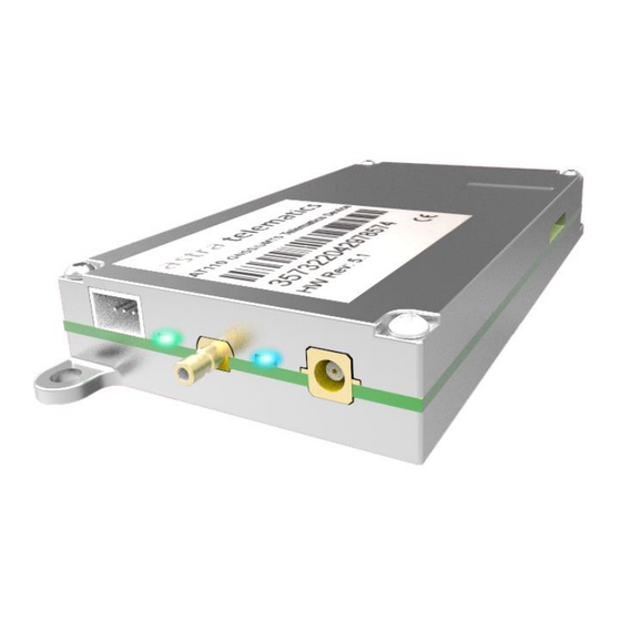
Product Overview The AT110 is a highly featured vehicle tracking device, housed in a sturdy aluminium enclosure with external GNSS/GSM/UMTS antennas. The AT110 incorporates the very latest technology, including the latest Cortex M3 ARM processor, ublox SARA-U2 penta-band 3G (GSM/UMTS) communication module and ublox EVA-M8M GNSS, supporting GPS, GALILEO, GLONASS &... -
Page 4: Technical Specifications
Technical Specifications UMTS/HSPA Communications: 800/850/900/1900/2100 MHz GSM/GPRS Communications: 850/900/1800/1900 MHz GSM Antenna: external GPS Antenna: external GPS Receiver: EVA-M8M L1 receiver: 72 channels Position accuracy: 2.5m CEP Receiver sensitivity: -164dBm (tracking) TTFF: Cold start 26 sec Hot start 1 sec Input voltage: 6 –... -
Page 5: Hardware Description
Hardware Description Dimensions SIM installation Note: fitting the SIM will trigger the AT110 to power up. The AT110 must be fitted with a SIM card (micro SIM, format 3FF) to allow access to a GSM/GPRS/UMTS network services. The SIM card is installed in a small slot in the side of the AT110. - Page 6 Power requirements The AT110 operates from a DC Voltage between 5 and 50 Volts. We recommend that a permanent power source is used to supply the AT110. If current drain is of concern, please refer to the power management section for options to minimise vehicle battery drain when stationary for long periods.
- Page 7 Interconnections For basic installations, the 3 wires provided on the standard power cable are all that is necessary, these provide power and ignition input (digital 1) using a 3 way cable which mates with the 3 way power header on the AT110 device. AT110 Power Connections and Colour Code Pin Number Application...
- Page 8 3.3V regulated output can be used as a reference voltage for external temperature sensors and used with the ADC1 input. Device Configuration / Settings For device configuration and related commands, please refer to the Astra Telematics Command Reference document, which describes our generic commands, for use with all our devices. Questions? If you have any problems, questions, please contact Astra Telematics technical support: support@gps-telematics.co.uk...
-
Page 9: Electrical Parameters
Electrical Parameters Operating Conditions Parameter Units Power Supply Input Voltage Digital Input High Voltage Threshold +5.0 Digital Input Low Voltage Threshold +2.0 Digital Maximum Voltage +30.0 Digital Maximum Current Absolute Maximum Ratings Parameter Units Power Supply Input Voltage Voltage on Digital 1-4 and ADC Inputs Voltage on Digital 5-6 (pull-down) +3.3 Voltage on RS232 RX... - Page 10 AT110-STD (Standard) Kit Contents Our AT110 standard kit is supplied with a CB110 power / ignition cable and an AE001 combined GSM-GPS antenna. CB110 Power / Ignition Cable This 3-way fused cable is used to connect a permanent voltage source (i.e. power), ground and an ignition-switched voltage source (i.e.
- Page 11 Note that each accessory is fitted with a unique connector, which matches only one of the available CB113 connectors, hence preventing incorrect termination. The following optional accessories are available from Astra Telematics and supported by direct connection to the CB113 cable: •...
Need help?
Do you have a question about the AT110V5 and is the answer not in the manual?
Questions and answers