Tekmar tekmarnet 552 Installation & Operation Manual
Hide thumbs
Also See for tekmarnet 552:
- Installation & operation manual (40 pages) ,
- User manual (13 pages) ,
- Quick setup manual (13 pages)
Table of Contents
Advertisement
Quick Links
tekmarNet
Installation & Operation Manual
Introduction
®
The tekmarNet
provides operation for:
•
One Stage Heat
A Watts Water Technologies Company
®
Thermostat 552
Thermostat 552
Features
•
Touchscreen
•
Bright Backlight
•
tekmarNet
•
Outdoor Temperature Display
•
Floor Temperature Display
•
7-Day, 4 Event Programmable
Schedule
•
Optimum Start
•
Scenes
•
Away Key
•
Air Group Member
•
Freeze Protection
•
Exercise Pump or Valves
•
Zone Synchronization
•
Two Auxiliary Sensor Inputs
Benefi ts
•
Simple to Use
•
Increased Comfort Through
Precise Temperature Control
•
Conserves Energy
•
Convenience Through Internet
Connectivity
•
Warm Radiant Floors
•
Protects Radiant Floors From
Over Heating
1 of 44
552_D
Zoning
Replaces: 08/11
®
Communication
© 2014
552_D - 09/14
09/14
Advertisement
Table of Contents

Related Manuals for Tekmar tekmarnet 552


Summary of Contents for Tekmar tekmarnet 552
- Page 1 552_D 09/14 tekmarNet ® Thermostat 552 Zoning Replaces: 08/11 Installation & Operation Manual Features Introduction • Touchscreen • Bright Backlight ® The tekmarNet Thermostat 552 provides operation for: ® • tekmarNet Communication • One Stage Heat • Outdoor Temperature Display •...
-
Page 2: Table Of Contents
Table of Contents Getting Started ....................4 Installation ......................4 Preparation ......................4 Removing The Thermostat Base ............... 5 Mounting The Thermostat Base ................. 5 Thermostat Wiring ....................6 Compatible Sensors ................... 7 Testing the Thermostat Wiring ................8 Mounting the Thermostat ................. 10 Cleaning the Thermostat .................. -
Page 3: Important Safety Information
Important Safety Information It is your responsibility to ensure that this thermostat is safely installed according to all applicable codes and standards. tekmar is not responsible for damages resulting from improper installation and/or maintenance. This is a safety-alert symbol. The safety alert symbol is shown alone or used with a signal word (DANGER, WARNING, or CAUTION), a pictorial and/or a safety message to identify hazards. -
Page 4: Getting Started
Getting Started Congratulations on the purchase of your new tekmar thermostat. This manual will step through the complete installation, programming and sequence of operation for this control. At the back, there are tips for control and system troubleshooting. Installation Preparation... -
Page 5: Removing The Thermostat Base
Removing The Thermostat Base To remove the thermostat base: • Locate the tab on the bottom of the thermostat. • Push the tab with either your thumb or with a screwdriver. • Lift the thermostat front away from the thermostat’s base. Mounting The Thermostat Base If a single gang box is used: •... -
Page 6: Thermostat Wiring
Thermostat Wiring The thermostat operates a single heating system zone and can be wired in four different ways. tekmarNet ® 2 - Allows the thermostat to be wired point-to-point using 2 wires to a ® tekmarNet 2 Wiring Center, House Control, or Zone Manager. This allows easy wiring for retrofit applications. -
Page 7: Compatible Sensors
-- -- - -- -- - - - - - - - -- - - - - - - - - - - - - - - - - - - - - Wiring - Stand Alone to Transformer and Zone Valve Install field jumper Zone Valve Optional Sensor 1... -
Page 8: Testing The Thermostat Wiring
If the thermostat display continues to be off, or is cycling on and off, there may be a fault on the thermostat. If a fault is suspected, contact your tekmar sales representative for assistance. Testing the Heat Zone Output Wiring 1. - Page 9 - - - - - -- - -- - - - - - - - - - - - - - - - - - - - - - - - - - - - - - - - - - - - - - - - - - - - - ®...
-
Page 10: Mounting The Thermostat
Mounting the Thermostat Thermostat Base Thermostat Front Push the thermostat front onto the thermostat base. Installation is now complete. Push Cleaning the Thermostat The thermostats’s exterior can be cleaned using a damp cloth. Moisten the cloth with water and wring out prior to wiping the control. Do not use solvents or cleaning solutions. -
Page 11: Switch Settings
Switch Settings Back of 1 2 3 1051-03 1051-03 Mmm YYYY Thermostat Lot # 12345 tekmarNet tNt 552 Switch One Stage Heat Thermostat 552 Settings One Stage Heat www.tekmarcontrols.com Power: 24 V ±10% 50/60 Hz 1.7 VA Power: tN2 or 24 V (ac) ±10% 1.8 VA Relay: 24 V (ac) 2 A Relay: 24 V (ac) 2 A Meets Class B:... -
Page 12: User Interface
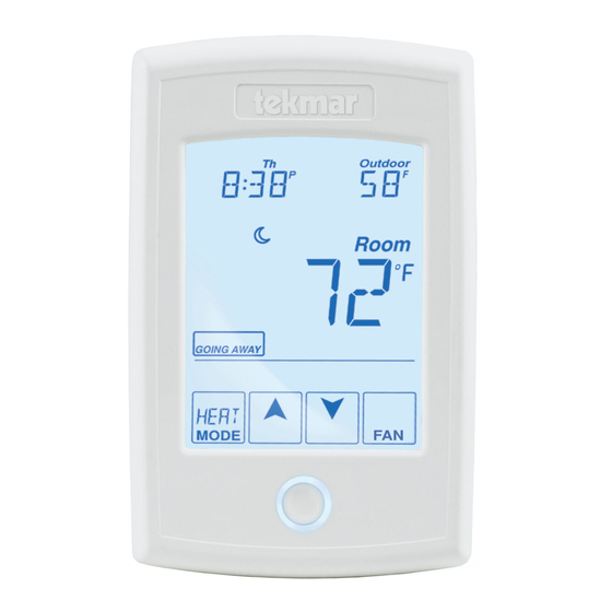
User Interface Home Screen The touchscreen of the 552 provides one touch access to these settings. Display the Adjust Floor or Outdoor the Time. temperature. Adjust the Schedule. Room Temperature. Away Key. Adjust the Temperature. Turn the Home Button. Heat on Return to the ‘Home’... -
Page 13: Programmable Settings
Programmable Settings Programming Menus Press and hold the Home button for 3 seconds to enter the programming menus. The thermostat returns to the last programming menu previously used. Press and hold for 3 seconds to access the programming menus. - - - - -- - -- - - - - - - - - - - -- - - -- - -- - - - - - - - - - -- -- - - - - ---- - - - - - - - - - - - - - - - - - - - - - - - - - - - - - - - - - Select a Programming Menu •... -
Page 14: Set Temp Menu
Set Temp Menu (1 of 3) Setting Display SET HEAT ROOM Room Set the room heating temperature during the event. Access Level: Installer, User Range: 40 to 95°F (4.5 to 35.0°C) Conditions: Room Sensor set to ON or Sensor 1 or Default: 70°F (21.0°C) Sensor 2 set to Room. - Page 15 Set Temp Menu (2 of 3) Setting Display SET HEAT FLOOR Set the floor heating temperature while in the Floor event. Access Level: Installer, User Range: 40 to 122°F (4.5 to 50.0°C) Conditions: Room Sensor set to OFF and Sensor 1 or Sensor 2 set to Floor, and Schedules are in Default: 65°F (18.5°C) use or Scenes are set to All or Guest.
- Page 16 Set Temp Menu (3 of 3) Setting Display FLOOR MAXIMUM Set the floor maximum temperature in order to protect the floor covering. Suggested settings: Tile = 90°F (32°C) Hardwood Floor = 85°F (29°C) Range: 40 to 122°F (4.5 to Access Level: Installer 50.0°C), OFF Conditions: Sensor 1 or Sensor 2 set to Floor, and either Room Sensor set to ON, or Room Sensor...
-
Page 17: Time Menu
Time Menu (1 of 2) Setting Display MINUTE Select the current time minutes. Access Level: Installer, User Range: 00 to 59 Conditions: Schedule is used or Clock is set to ON. Default: 00 HOURS Select the current time hours. Access Level: Installer, User Range: 12 AM to 11 PM or 00 to 23 Conditions: Schedule is used or Clock is set to ON. - Page 18 Time Menu (2 of 2) Setting Display DAYLIGHT SAVINGS TIME Select if daylight savings time is observed. Access Level: Installer, User Range: OFF or ON Conditions: Clock setting is set to ON. Default: ON TIME MODE Select either 12 or 24 hour time format. Access Level: Installer, User Range: 12 or 24 hour Conditions: Clock setting is set to ON.
-
Page 19: Schedule Menu
Schedule Menu (1 of 2) The schedule menu can operate on a 24 hour or 7 day repeating schedule. When a 24 hour schedule is selected, “SuMoTuWeThFrSa” is shown on the top of the screen to show that the event time applies to all days of the week. When a 7 day schedule is selected, each individual day of the week is shown with the event time. -
Page 20: Display Menu
Schedule Menu (2 of 2) Setting Display SCHEDULE Select if the thermostat should change the temperature automatically using a programmable schedule. OFF = Programmable schedule is not used. Zone = Applies to this thermostat only. Master 1, 2, 3, 4 = In charge of one of four available network schedules. -
Page 21: Scenes Menu
Display Menu (2 of 2) Setting Display BACKLIGHT Select how the display backlight operates. ON = Always full brightness. DIM = Dim when inactive, on when touched. = Dim in , off in . On when touched. = On in , off in . -
Page 22: Monitor Menu
Monitor Menu (1 of 3) Setting Display ROOM AVERAGE Current room temperature. Displays the average if there are multiple room sensors. Range: -58 to 212°F (-50.0 to Access Level: Installer 100.0°C) Conditions: Sensor 1 or 2 is set to Room. Default: Not applicable. - Page 23 Monitor Menu (2 of 3) Setting Display OUTDOOR HIGH The highest recorded outdoor air temperature measurement. Touch the number and touch the ENTER key to reset. Range: -76 to 149°F (-60.0 to Access Level: Installer, User 65.0°C) Conditions: Setup menu setting SENSOR 1 is set to Outdoor or an outdoor temperature is available on Default: Not applicable.
-
Page 24: Toolbox Menu
Monitor Menu (3 of 3) Setting Display FLOOR LOW The lowest recorded floor temperature measurement. Touch the number and touch the ENTER key to reset. Range: -76 to 149°F (-60.0 to Access Level: Installer, User 65.0°C) Conditions: Setup menu setting SENSOR 1 or 2 is Default: Not applicable. - Page 25 Toolbox Menu (2 of 3) Setting Display STATUS INFO Displays the current status of the thermostat including ® any overrides from the tekmarNet system control. Toggles between “Status Info” and the current status. ® Override W1 = The tekmarNet system control is either forcing the W1 relay on or off.
- Page 26 Toolbox Menu (3 of 3) Setting Display SOFTWARE AND TYPE VERSION Displays the software version and the tekmar type number. Access Level: Installer, User, Limited, Secure Range: 552 Conditions: Always available. Default: 552 DEVICE COUNT ® Provides a count of all the tekmarNet thermostats ®...
-
Page 27: Setup Menu
Setup Menu (1 of 2) Setting Display SENSOR 1 Select to the type of sensor connected to auxiliary sensor input 1. Range: OFF, ROOM, FLOR (floor), Access Level: Installer OUT (outdoor) Conditions: Always available. Default: OFF SENSOR 2 Select to the type of sensor connected to auxiliary sensor input 2. - Page 28 Setup Menu (2 of 2) Setting Display W1 THERMAL MOTOR Select whether the first stage of heat W1 operates a thermally actuated zone valve (wax actuator). When set to ON, there is a 3 minute delay before operating the pump and any heat sources. Access Level: Installer Range: OFF or ON Conditions: Setup menu setting W1 TERM is set to...
-
Page 29: Sequence Of Operation
Sequence of Operation Section A Heating Operation -- - ---- - - - - - - - - - - - - - - - - - - -- - - -- - - - - -- -- - -- -- - - - ---- - - - - - ---- - - - - - - - - - - - - - - - - - - - - - - - - - - - - - - - - - - Set Heat Temperature When using only a room temperature sensor, the thermostat operates the heating... - Page 30 -- - - -- - ----- - - - - - - - - - - - - - - - - - - - - - - - - - - -- - -- -- -- - -- - - -- - - ---- - - - - - ---- - - - - - - - - - - - - - - - - - - - - - - - - - - - - - - - - - - - Freeze Protection The thermostat operates the heat whenever the room or floor temperature falls...
-
Page 31: Air Group Operation
Section C Air Group Operation In order to prevent heating and cooling at the same time, this thermostat can operate ® together with other thermostats on a tekmarNet system to form an air group. On older model thermostats the air group functionality was previously described as a cool group. -
Page 32: Temperature Adjustment
Section E Temperature Adjustment - - - - - - - - - - - -- -- - - - - - - - - - - - - - - -- - - - - - - - - - - - - - - - - - - - - - - - - - - - - - - - - - Permanent Adjustment - No Schedule When no programmable schedule is used, touch the up or down arrows to permanently set the “Set Heat”... -
Page 33: Programmable Schedules
Section F Programmable Schedules Lowering the room temperature setting reduces the amount of fuel required to heat the building resulting in energy savings. When operating on a programmable schedule, a or a symbol is shown in the home menu. The indicates the current operating temperature. -
Page 34: Scenes (System Override)
Section G Scenes (System Override) Scenes provide an easy way to save energy while away on vacation, or override a programmable schedule when plans change. - -- - - -- --- ---- - -- -- --- -- - - - - - - - - - - - - -- - -- -- - -- - -- -- - -- -- - -- - -- -- --- --- ---- ---- --- --- - - - - - - - - - - - - - - - - - - - - - - - - - - - - - - - - - - Away Key This thermostat includes an Away Key to quickly turn down the heating temperature... -
Page 35: Secondary Temperature Display
- - - - - - - - - - - - - - - -- - -- - - - - - - - - - - - - - - - - - - - - - - - - - - - - - - - - - - - - - - Recommendation on How to Use Scenes Choosing how to use scenes depends on the needs and lifestyle of the customer using the building. -
Page 36: Access Levels
Section I Access Levels The thermostat Toolbox menu supports four access levels: Installer (INST), User (USER), Limited (LTD), and Secure (SEC). The access level can be adjusted when the thermostat is unlocked. There are two locations to lock the thermostat: 1) Locally on the back of the thermostat using the Lock switch 2) Globally on the tekmarNet ®... -
Page 37: Troubleshooting
Troubleshooting Error Messages (1 of 5) Error Message Description SETUP MENU SAVE ERROR The thermostat failed to read the Setup menu settings from memory and has reloaded the factory default settings. The thermostat stops normal operation until all settings in the Setup menu are checked except to provide freeze protection. - Page 38 Error Messages (2 of 5) Error Message Description SCENES MENU SAVE ERROR The thermostat failed to read the Scenes menu settings from memory and has reloaded the factory default settings. The thermostat continues to operate normally while displaying this error. To clear the error, set the access level to Installer and check all settings in the Scenes menu.
- Page 39 ® The error cannot be field repaired. Contact your tekmar sales representative for repair procedures. ROOM SENSOR OPEN CIRCUIT ERROR Due to an open circuit, the thermostat is unable to read the built- in room temperature sensor.
- Page 40 Error Messages (4 of 5) Error Message Description SENSOR 2 OPEN CIRCUIT ERROR Due to an open circuit, the thermostat is unable to read auxiliary Sensor 2. The thermostat stops normal operation if Sensor 2 is the only active Room or Floor sensor or if a Floor Maximum temperature has been set.
- Page 41 Error Messages (5 of 5) Error Message Description ERROR AT THERMOSTAT There is an error on a different thermostat or setpoint ® control connected to the tekmarNet system and not on this thermostat. 01 to 24 = There is an error on a thermostat or setpoint control ®...
-
Page 42: Frequently Asked Questions
Frequently Asked Questions Symptom Look for... Corrective Action indicates heat relay W1 is on. If the is displayed and there is no heat, check if the zone valve or zone pump is operating. No heat The thermostat is in the Off mode. Touch the mode key to change to Heat. -
Page 43: Technical Data
Sensors: NTC thermistor, 10 kΩ @ 77°F (25°C ±0.2°C) ß=3892 – Included None – Optional tekmar type # 070, 071, 072, 073, 076, 077, 078, 079, 082, 084 A Watts Water Technologies Company 43 of 44 © 2014 552_D - 09/14... -
Page 44: Limited Warranty And Product Return Procedure
Prod- uct was not installed in compliance with tekmar’s instructions and / or the local codes and ordinances; or if due to defective installation of the Product; or if the Product was not used in compliance with tekmar’s instructions.
Need help?
Do you have a question about the tekmarnet 552 and is the answer not in the manual?
Questions and answers