Advertisement
Quick Links
- Data Brochure
Programmable Thermostats 510 - 512 : Operation
Table of Contents
Display Operation....................................................... pg 1
General ....................................................................... pg 1
Sequence of Operation .............................................. pg 2
Type 510 (One Stage Heating) .......................... pg 2
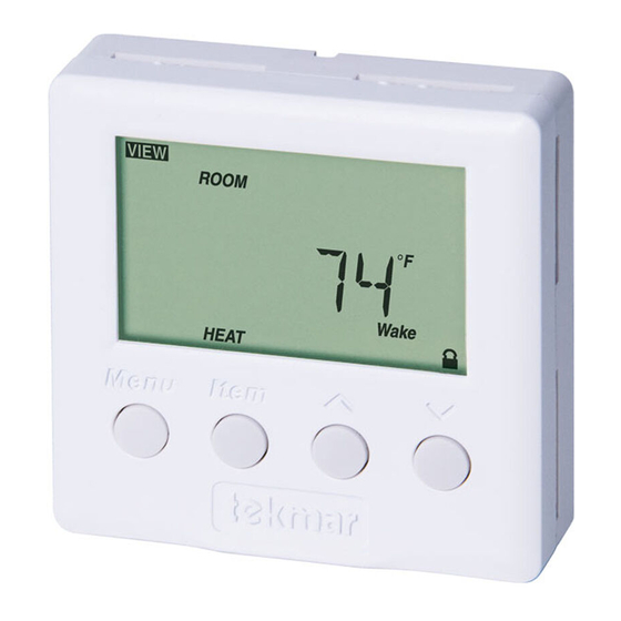
Display / Keypad Operation
The thermostat's display has four distinct fields. These fields are the Menu field, the Item field, the Number field and the Status
field. The four buttons on the face of the thermostat are used to navigate through the menus and items to view and / or adjust the
desired settings.
Displays the
current
menu
Displays the current
status of the
thermostat's inputs,
outputs and operation
General
CYCLES PER HOUR (HEAT CYCLE and COOL CYCLE)
The thermostat operation is based on cycles per hour. The number of cycles per hour is adjustable through the HEAT CYCLE and
COOL CYCLE settings in the Adjust menu. During each cycle that heating or cooling is required, the thermostat turns on the Heat or
Cool relay(s) for a calculated amount of time. This amount of time is the "on time". The on time is calculated based on the require-
ments of the zone. If the zone requires more heating or cooling, the appropriate on time is increased. If the zone requires less heat
or cooling, the appropriate on time is reduced.
In order to prevent short cycling of the heating relay(s), the thermostat ensures
that the relay(s) remains on or off for a minimum amount of time. In order to pre-
vent short cycling of the Cool relay, the minimum cooling on time and minimum
cooling off time settings are adjusted in the Adjust menu of the 512.
An Auto Cycle setting is available for both the heating cycle and the cooling cycle.
This setting allows the thermostat to determine the best number of cycles per
hour that balances both temperature swings and equipment cycles.
Menus ......................................................................... pg 5
Error Messages .......................................................... pg 7
Displays an abbreviated
name of the selected item
Displays the current value
of the selected item
Selects Menus, Items
and adjusts settings
1 of 8
Type 512 (Two Stage Heating) .......................... pg 3
Type 512 (Heat / Cool) ....................................... pg 4
Display Symbols
Warning
Displays when an error exists.
Access Level
Displays when in the user
access level.
Early Start
Displays when the thermostat
is in early start.
Heat One
Displays when the heat one
contact is on.
Heat Two
Displays when the heat two
contact is on.
Cool One
Displays when the cool one
contact is on.
Cycles Per Hour
on
on
off
⇐ Cycle Length ⇒
© 2002
D 510A
03/02
on
off
off
Time
D 510A - 03/02
Advertisement

Related Manuals for Tekmar 512


Summary of Contents for Tekmar 512
-
Page 1: Table Of Contents
In order to pre- vent short cycling of the Cool relay, the minimum cooling on time and minimum cooling off time settings are adjusted in the Adjust menu of the 512. ⇐ Cycle Length ⇒... -
Page 2: Sequence Of Operation
ACCESS LEVELS The tekmar Programmable Thermostat has two access levels. These access levels restrict the number of items available in the menus of the thermostat. The two access levels are User and Installer. -
Page 3: Type 512 (Two Stage Heating)
If an air or slab sensor is active in the Off mode, a freeze protection is enabled that allows the Heat relay to be operated to keep the zone above 35°F (2°C). TYPE 512 (Two Stage Heat) Two Stage The two stage mode of operation is selected using the DIP switch located on the circuit board inside the thermostat. -
Page 4: Type 512 (Heat / Cool)
Note: If an air or slab sensor is active in the Off mode, a freeze protection is enabled that allows the relays to be operated to keep the zone above 35°F (2°C). TYPE 512 (Heat / Cool) The Heat / Cool mode of operation is selected using the DIP switch located on the circuit board inside the thermostat... - Page 5 View Menu (1 of 1) Slab Room Target The current slab temperature. The current desired air temper- ature for the space. This item (Must have an active slab sensor. If is only available in the Installer two slab sensors are present, this is access level.
- Page 6 Adjust Menu (2 of 3) Room Cool Wake Slab Minimum Sleep Desired temperature for cooling Minimum slab temperature during Wake. during Sleep. (Must have an active air sensor (Must have an active slab sensor.) and be set to either Cool or Auto) OFF, 34 to 122°F (OFF, 1.0 to 50.0°C) 35 to 100°F (1.5 to 38.0°C) Room Cool UnOcc...
-
Page 7: Menus
Adjust Menu (3 of 3) Cooling Interlock Early Start Selects the time delay between Selects whether or not the Early the heating and cooling relays. Start feature is active. This item This item is only available in the is only available in the Installer Installer access level. - Page 8 The tekmar Limited Warranty to the Purchaser on the Products sold hereunder is a man- which have not been authorized by tekmar; or if the Product was not installed in compliance with ufacturer’s pass-through warranty which the Purchaser is authorized to pass through to tekmar’s instructions and/or the local codes and ordinances;...
- Page 9 ——————— STEP ONE GETTING READY Check the contents of this package. If any of the contents are missing or damaged, please contact your wholesaler or tekmar sales representative for assistance. Type 510 Includes: One Programmable Thermostat 510, Data Brochure D 510A, Data Brochure D 510B, User Brochure U 510...
- Page 10 Heat Relay (510 and 512) The Heat (1) terminals (6 and 7) are an isolated output. There is no power available on these terminals from the thermostat. These terminals are to be used as a switch for a 24 V (ac) circuit. This circuit can operate a low current 24 V (ac) device directly or an external relay to enable a line voltage or high current device.
- Page 11 Zone Pump 24 V (ac) 24 V (ac) Class II Class II Transformer Transformer WIRING THE 512 One Stage Heat with Zone Valve and Cooling One Stage Heat with Zone Pump and Cooling Unpowered Relay Cooling Cooling Zone Zone Pump...
- Page 12 Web Site: www.tekmarcontrols.com Product design, software and literature are Copyright © 2002 by: All specifications are subject to change without notice. 4 of 4 tekmar Control Systems Ltd. and tekmar Control Systems, Inc. Printed in Canada. D 510B - 03/02.
Need help?
Do you have a question about the 512 and is the answer not in the manual?
Questions and answers