Tekmar 518 Installation & Operation Manual
Hide thumbs
Also See for 518:
- Installation and operation manual (12 pages) ,
- Quick setup manual (8 pages) ,
- Quick setup manual (12 pages)
Table of Contents
Advertisement
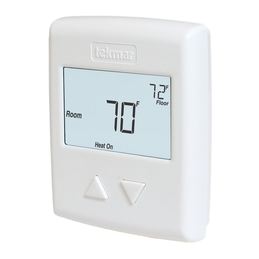
Thermostat 518
Installation & Operation Manual
Introduction
The Thermostat 518 accurately controls the
room temperature for a hydronic heating
zone using Pulse Width Modulation (PWM)
technology. Simple up and down buttons
and a display with large type make this
thermostat easy to read and use. The 518
automatically detects a single auxiliary
sensor to measure either outdoor, floor
or remote room temperature. This easy to
install thermostat is a direct replacement
for tekmar Thermostats 507 and 508.
A Watts Water Technologies Company
Energy Saving Features
•
Auto Heating Cycle
Additional Features
•
Radiant Floor Heating
•
Pulse Width Modulation
•
Auxiliary Sensor Input
•
Outdoor & Floor Temperature
Display
•
Backlight
•
Freeze Protection
1 of 12
518 _ D
Zoning
Replaces: New
© 2013
518_D - 03/13
03/13
Advertisement
Table of Contents

Related Manuals for Tekmar 518


Summary of Contents for Tekmar 518
-
Page 1: Energy Saving Features
Pulse Width Modulation (PWM) technology. Simple up and down buttons and a display with large type make this thermostat easy to read and use. The 518 automatically detects a single auxiliary sensor to measure either outdoor, floor or remote room temperature. This easy to install thermostat is a direct replacement for tekmar Thermostats 507 and 508. -
Page 2: Table Of Contents
Symbols Description .......7 Getting Started ® Congratulations on the purchase of your new tekmar thermostat. This manual will step through the complete installation, programming and sequence of operation for this control. At the back, there are tips for control and system troubleshooting. -
Page 3: Removing The Thermostat Base
- - - - - - - - ---- - --- - - - - - - - - - - - - - - - - - - - - -- -- - - -- - - - -- - - - - - - ---- - - - - - -- - - - - - - - - - - - - - - - - - - - - - - - - - - - - - - - - - - Materials Required •... -
Page 4: Mounting The Thermostat
Mounting The Thermostat Stud Adapter Plate 012 Thermostat Base Thermostat ” Front (83 mm) Gang If a single gang box is used: • Adapter Plate 012 is required (sold separately). • Feed the wiring through the hole in the adaptor plate and the thermostat base. •... -
Page 5: Thermostat Wiring
Thermostat Wiring - -- - - --- - - ---- - --- - - - - -- - - - - - - - - - - - - - -- - - - -- -- - -- -- - --- - - - -- -- -- - - - - - - - - - - ---- - - - - - - - - - - - - - - - - - - - - - - - - - - - - - - - - - - - - - - Zone Valve Install field... -
Page 6: Testing The Thermostat Wiring
DC power supplies the voltage should measure between 10 to 30 V (dc). 3. If the voltage on the R and C wire terminations is continuous and the thermostat display is not on, the thermostat may have a fault. Contact your tekmar sales representative for assistance. -
Page 7: User Interface
User Interface Home Screen Symbols Description HEAT ON Heat is turned on. The floor is at or below the floor minimum temperature. MODE OFF The heating system is off. The floor has reached the WARNING SYMBOL floor maximum temperature. Indicates an error is present. A Watts Water Technologies Company 7 of 12 ©... -
Page 8: Sequence Of Operation
Sequence of Operation Heating Operation To change the heat temperature setting, push the button to select a preferred temperature setting. The Heat On symbol is shown on the display when the thermostat is heating. The heat can cycle on and off within +/- 1.5°F (1°C) of the temperature setting. The floor and air heating can be shut off by holding the button until Set Room is Off. -
Page 9: Programmable Settings
Programmable Settings Setting Display User settings. Press the buttons together for 3 seconds to enter and advance to the next setting. MODE Select heat or off. Range: HEAT, OFF Default: HEAT UNITS Select the temperature units. Range: °F or °C Default: °F LIGHT Select when the display back light should operate. -
Page 10: Troubleshooting
The built-in air temperature sensor has an open circuit fault. Do not confuse this error with the auxiliary room sensor short circuit error. This error cannot be field repaired. Contact your wholesaler or tekmar Room sales representative for details on repair procedures. -
Page 11: Frequently Asked Questions
30 V (ac/dc) 2 A, Class 2 circuits Sensor NTC thermistor, 10 kΩ @ 77°F (25°C ±0.2°C) ß=3892 – Included None – Optional tekmar type # 070, 072, 073, 076, 077, 079, 084 A Watts Water Technologies Company 11 of 12 © 2013 518_D - 03/13... -
Page 12: Limited Warranty And Product Return Procedure
(24) months from the production date. The liability of tekmar under the Limited Warranty shall be limited to, at tekmar’s sole discretion: the cost of parts and labor provided by tekmar to repair defects in materials and / or workmanship of the defective product; or to the exchange of the defective product for a warranty replacement product;...
Need help?
Do you have a question about the 518 and is the answer not in the manual?
Questions and answers