DriSteem HUMIDI-TECH Installation Instructions And Maintenance Operations Manual
Electric steam humidifiers
Hide thumbs
Also See for HUMIDI-TECH:
- Installation, operation and maintenance manual (52 pages) ,
- Service kit manual (18 pages) ,
- Field conversion instructions (4 pages)

Related Manuals for DriSteem HUMIDI-TECH


Summary of Contents for DriSteem HUMIDI-TECH
- Page 1 READ AND SAVE THESE INSTRUCTIONS ® HUMIDI-TECH and ® HUMIDI-TECH DI ELECTRIC STEAM HUMIDIFIERS Installation Instructions Maintenance Operations Manual UL LISTED CUL LISTED...
-
Page 2: Table Of Contents
Familiarizing yourself with this manual will help ensure proper operation of the equipment for years to come. This manual covers the installation and maintenance procedures for both the HUMIDI-TECH and HUMIDI-TECH DI humidifiers. -
Page 3: Humidi-Tech Diagrams
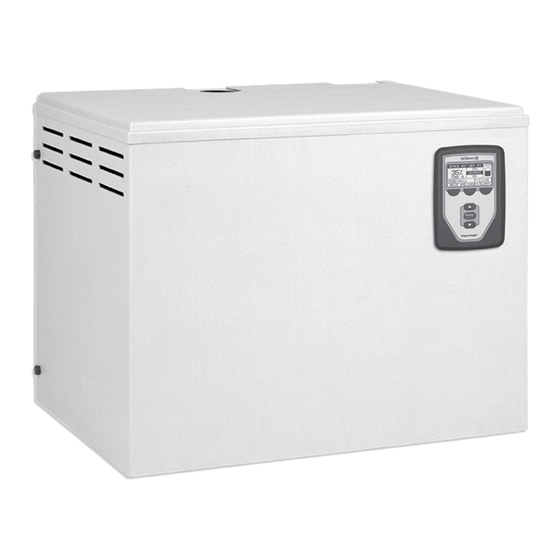
® HUMIDI-TECH DIAGRAMS Figure 3-1: HUMIDI-TECH Humidifier The HUMIDI-TECH unit requires water conductivity of at least 100 μS/cm (34 mg/l) to operate. It will not operate with water treated by reverse osmosis or 38 mm or 50 mm flexible deionization processes. -
Page 4: Installation
Humidifier The HUMIDI-TECH humidifier is designed to hang on When mounting on a stud wall, locate studs and a wall, and should be installed in a space located near position mounting bracket in place so that each of the an air duct system. -
Page 5: Mounting Dispersion Tube With Condensate Drain Line
INSTALLATION HUMIDI-TECH ® Mounting Tube Figure 5-1: Single Tube with Condensate Drain Line • Mount dispersion tube level. • Orient dispersion tube so that tubelets are pointed straight up. Insertion Length Pre-molded High 80 mm Temperature Resin Tubelets Mounting 80 mm... -
Page 6: Connecting Dispersion Tube To Humidifier
INSTALLATION Failing to follow these recommendations may result in Connecting Dispersion Tube to Humidifier excessive back pressures being imposed on the • Connection can be made with vapor hose or rigid humidifier. This may lead to dispersion tube(s) spitting, tubing. steam blowing through water seals, or leaking gaskets. -
Page 7: Piping
PIPING Water make-up piping may be of any code-approved The final connection sizes are 20 mm O.D. for evapo- material (copper, steel, or plastic). The final connection rator drain and 13 mm for cabinet drain. These con- size is 1/4". In cases where water hammer may be a nection sizes should not be reduced. -
Page 8: Wiring
All wiring must be in accordance with all ® Figure 8-1: Field Wiring Requirements governing codes, and with HUMIDI-TECH or HUMIDI-TECH DI wiring diagram. The diagram is located inside the removable front HUMIDI-TECH Sub Panel Power Block panel on the right-hand side of the humidifier cabinet. -
Page 9: Electrical Specifications And Capacities/Dimensions
13.6 16.3 21.8 28.6 46.3 Top View Figure 9-1: HUMIDI-TECH ® Unit Dimensions (All measurements shown in millimetres.) 400 mm Note: For models VM 16 and 25, dispersion tubes will be equipped with a condensate tube when a hose kit is 140 mm used. -
Page 10: Area-Type Application Using Space Distribution Unit (Sdu)
Mounting the SDU The SDU may be placed directly on top of the HUMIDI-TECH cabinet or mounted on a wall. A wall mounting bracket and two 10 mm lag bolts are pro- vided with each fan unit. (See page 4 for mounting instructions.) - Page 11 AREA-TYPE APPLICATION USING SDU Table 11-1 lists the recommended minimum vertical Table 11-1: SDU Visible Fog Travel (RISE) and horizontal (CARRY) clearances for area- type humidifiers at 50% and 60% RH of the space. 50% RH 60% RH The SDU contains a 735 m /h blower and a 300VA Humidifier Rise...
-
Page 12: Start-Up And Operation
Figure 12-1: Electronic Probe Control for Main- Upon activation, the following sequence occurs: taining Proper Water Level (HUMIDI-TECH Only) 1. The drain valve opens and begins to drain surface water and minerals from the evaporating chamber. - Page 13 Let the fill water run until the able, a pressure-reducing valve or shock arrester should tank is cooled then shut off the contractor installed be installed. Even though the HUMIDI-TECH has an supply water valve. internal 25 mm air gap, some local codes may require a vacuum breaker.
-
Page 14: Maintenance
To Service: HUMIDI-TECH DI 1. Shut off electrical power to the unit. Using the key, The HUMIDI-TECH DI unit uses DI/RO water. Because unlock and remove the large front panel. Drain the these water types are mineral-free, cleaning the evapo- evaporating chamber by manually opening the rating chamber should not be necessary. - Page 15 12. Reconnect connector tube and flexible hoses. 13. Return drain valve handle to closed position. 14. Replace front panel and turn on electric power. ® 15. HUMIDI-TECH DI is again ready to humidify. Off-Season Shut-Down Procedure 1. Switch off electric power.
-
Page 16: Humidi-Tech Trouble-Shooting Guide
® HUMIDI-TECH TROUBLE-SHOOTING GUIDE CONTROL PANEL LIGHTS PROBLEM FILL READY DRAIN POSSIBLE CAUSE RECOMMENDED ACTION WATER Humidifier will Control transformer Verify control voltage across secondary not heat leads of transformer. Reset transformer circuit breaker. Humidistat is not calling Set humidistat to call. Inspect for faulty humidistat. -
Page 17: Humidi-Tech Di Trouble-Shooting Guide
® HUMIDI-TECH DI TROUBLE-SHOOTING GUIDE PROBLEM READY POSSIBLE CAUSE RECOMMENDED ACTION WATER Humidifier will Control transformer Verify control voltage across secondary leads of not heat transformer. Reset transformer circuit breaker. Humidistat is not calling Set humidistat to call. Inspect for faulty humidistat. -
Page 18: Replacement Parts
REPLACEMENT PARTS ® Figure 18-1: HUMIDI-TECH VM - 2, 4, 6, 8, 10, 12, 16 VM - 25 and 34 OM-214A... - Page 19 REPLACEMENT PARTS ® Table 19-1: HUMIDI-TECH (see figure 18-1) No. Description Qty. Part No. Tank 160012* Cover Thermo Cut-Out 409560-001 Cover, Heater Terminal 160750* Gasket, Cover 160695* Heater 409600* Knob, T-Handled Utility 700725 Connector, 10mm flex. 407127-038 Valve, Solenoid Fill...
- Page 20 REPLACEMENT PARTS ® Figure 20-1: HUMIDI-TECH VM - 2, 4, 6, 8, 10, 12, 16 VM - 25 and 34 OM-215A...
- Page 21 REPLACEMENT PARTS ® Table 21-1: HUMIDI-TECH DI (see figure 20-1) No. Description Qty. Part No. Tank 160012* Cover Thermo Cut-Out 409560-001 Cover, Heater Terminal 160750* Gasket, Cover 160695* Heater 409600* Knob, T-Handled Utility 700725 Elbow, 6mm 90° (VMDI 2-16) 200580...
- Page 22 REPLACEMENT PARTS ® Table 22-1: Subpanel for HUMIDI-TECH HUMIDI-TECH DI No. Description Qty. Part No. Microprocessor Board, LW430 408641 Transformer Contactor 407001-005 Circuit Breaker, 2-Pole 4 amp 406775-001 Terminal Block, 3-Pole contact 408300-002 Grounds Bar 408255 Switch, Door Interlock #2HBA-5...
-
Page 23: Maintenance Service Record
MAINTENANCE SERVICE RECORD DATE INSPECTED PERSONNEL OBSERVATION ACTION PERFORMED... -
Page 24: Two-Year Limited Warranty
Continuous product improvement is a policy of DRI-STEEM therefore, product features and specifications are subject to change without notice. 14949 Technology Drive • Eden Prairie, MN 55344 USA Telephone: +1 612 949 2415 Fax: +1 612 949 2933 E-Mail: sales@dristeem.com Printed on recycled paper with 3ULQWHGRQUHF\FOHGSDSHUZLWKDJULEDVHGLQNV agri-based inks.
Need help?
Do you have a question about the HUMIDI-TECH and is the answer not in the manual?
Questions and answers