
Related Manuals for DriSteem STS SERIES


Summary of Contents for DriSteem STS SERIES
- Page 1 READ AND SAVE THESE INSTRUCTIONS ® S team -to -S team Hu m idi fie r Installation, Operation, and Maintenance Manual...
- Page 2 HVAC and electrical contractors and in compliance with local, state, federal, and governing codes. Improper installation can cause property damage, severe personal injury, or death as a result of electric shock, burns, or fi re. DriSteem technical support: 800-328-4447 ®...
- Page 3 Warnings and cautions WARNING Disconnect electrical power Disconnect electrical power before installing supply wiring or performing service or maintenance procedures on any part of the humidifi cation system. Failure to disconnect electrical power could result in fi re, electrical shock, and other hazardous conditions.
-
Page 4: Table Of Contents
Wall brackets ........9 • DriSteem Humidifi cation System Design H-legs . - Page 5 Table of contents OPERATION ............. . Start-up procedure .
-
Page 6: Overview
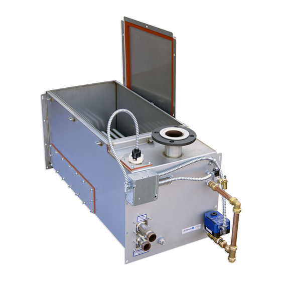
STS tap/softened water humidifi ers can be converted in the fi eld for use with DriSteem warranty. RO/DI water, and STS RO/DI water humidifi ers can be converted in the fi eld for use with tap/softened water. Contact your DriSteem representative or Total hardness distributor for parts and instructions. - Page 7 OVERVIEW Product overview FIGURE 3-1: STS HUMIDIFIERS FIGURE 3-2: WATER LEVEL CONTROL FOR TAP/SOFTENED WATER HUMIDIFIER Notes: • Drain piping material must be suitable for 212 °F (100 °C) water. • See the piping drawings on Pages 22 through 25. Tap/softened water STS humidifi...
-
Page 8: Dimensions
OVERVIEW Dimensions FIGURE 4-1: DIMENSIONS, STS MODELS 25, 50, 100, 200, AND 400 (WITH COPPER OR STAINLESS STEEL HEAT EXCHANGERS) Front view Side view Mounting holes: Models 25–100: 5/16" (8 mm) slot Models 200 & 400: 1/2" (12 mm) slot OM-932 OM-931 Notes:... - Page 9 OVERVIEW Dimensions Table 5-1: Dimensions, STS with copper heat exchangers STS model* Description 100C 400C 800C See drawings in Figures 4-1 and 4-2 inches inches inches inches inches A Height** 19.50 19.50 19.50 19.50 29.75 B Width 14.75 14.75 19.25 30.25 30.25 C Length...
-
Page 10: Capacities, Electrical Specifications, And Weights
OVERVIEW Capacities, electrical specifi cations, and weights Table 6-1: STS humidifier models and capacities with copper heat exchangers Steam pressure at connection to STS steam valve (valve provided by DriSteem) STS models 5 psi (34 kPa) 10 psi (69 kPa) -
Page 11: Selecting A Location
INSTALLATION Selecting a location When selecting the location of the humidifi er, consider the following: • Maximum ambient temperature for control cabinet is 104 °F (40 °C). • Noises inherent to operation such as STS water fi ll cycles • Easy access for maintenance •... -
Page 12: Mounting Methods
25 and 50 15.5 waste. Do not drain humidifi er directly into drip pan. Install water seal as shown on DriSteem optional wall Pages 22 through 25. brackets (two required) 5. Drip pan (by installer) recommended in overhead installations to prevent possible water damage to equipment below. -
Page 13: Mounting The Humidifier
Support legs, trapeze hanger, and wall brackets are not available for STS models 200, WALL BRACKETS 400, and 800. See Figure 8-3. DriSteem does not recommend mounting STS model 200, 400, or 800 with wall brackets. DriSteem recommends using 3/8" (M10) fasteners. Table 9-1: STS mounting options •... -
Page 14: Weather Cover
INSTALLATION Weather cover FIGURE 10-1: WEATHER COVER EXPLODED VIEW Table 10-1: Weather cover weights Panel Weather cover size Panel STS 25 to 100 Panel STS 200 to 800 mc_012511_1600 OM-7466 mc_012511_1606 Panel Hinged door Hinged door FIGURE 10-2: WEATHER COVER DIMENSIONS OM-7465 mc_012511_1607 Table 10-2:... - Page 15 ETL Testing Laboratories, Inc., and is listed to UL Standard 1995 and certifi ed to CAN/CSA Standard C22.2 No. 236. The weather cover is fully assembled at the DriSteem factory. INSTALLATION NOTES Open the hinged doors to make necessary connections to the humidifi er. Refer to the installation section of this manual for all elec tri cal, supply water, and drain con nec tion requirements.
-
Page 16: Outdoor Enclosure
2" (hole dia. 63.5 mm) for STS models 200-800. Run the electrical power into the en clo sure at these knockouts. 3. All piping from the STS unit to the steam outlet is stainless steel pipe. Depending on the application, tubing or DriSteem steam hose is recommended for interconnecting piping from steam outlet to dispersion assembly. -
Page 17: Electrical Specifications
INSTALLATION Outdoor Enclosure FIGURE 13-1: OUTDOOR ENCLOSURE, TOP VIEW Valve access door: • Models 25-100 have one access door • Models 200-800 have two access doors Valve access door Pipe chase extending 1" (25 mm) above enclosure fl oor Optional steam outlet (exits enclosure through pipe chase) Valve section heater Intake ventilation fan... - Page 18 3. DriSteem recommends copper or iron drain piping for Outdoor Enclosures. On a loss of power the tank water will drain, but not be cooled by the Drane-kooler because of the fi eld supplied safety shut-off valves. If it is critical to keep the Drane-kooler functional in the case of a power loss, disconnect the Drane-kooler and relocate it down inside the conditioned space of the building.
-
Page 19: Mounting
INSTALLATION Outdoor Enclosure FIGURE 15-1: STS OUTDOOR ENCLOSURE, TOP VIEW Valve access door: • Models 25-100 have one access door • Models 200-800 have two access doors Valve access door Pipe chase extending 1" (25 mm) above enclosure fl oor Optional steam outlet (exits enclosure through pipe chase) Valve section heater... - Page 20 INSTALLATION Outdoor Enclosure MOUNTING (CONTINUED) FIGURE 16-1: OUTDOOR ENCLOSURE • There are four knockouts on the right and left side of the enclosure. It is MOUNTING OPTIONS recommended that electrical power is run into enclosure at these knockouts. Flush • Outdoor Enclosure is designed for lifting by two methods: –...
-
Page 21: Sts Outdoor Enclosure Sequence Of Operation
• All piping from humidifi er to steam outlet is stainless steel pipe. Depending continue to run and once the enclosure on the application, tubing or DriSteem steam hose is recommended for temperature falls below 130 °F (54 °C), the interconnecting piping from steam outlet to dispersion assembly. -
Page 22: Alternate Water Seal And Drain Valve Piping
If the proximity of a drain requires the humidifi er drain and skim water to be lifted by a pump, DriSteem offers a condensate pump option. A check valve is required on the discharge of the pump. Electrical power for the pump is independent of the humidifi... - Page 23 1. See Warning and Caution at right. connection: 2. Cut drain line to length for insertion depth shown below for your ProBite • In addition to DriSteem drain connector size. Cut must be clean and smooth. piping material requirements on 3.
-
Page 24: Fill
INSTALLATION Piping: Fill WATER SUPPLY PIPING All STS humidifi er models have a 1" (25 mm) internal air gap to prevent back siphoning into a potable water system. However, some governing codes may require additional protection such as a vacuum breaker or backfl ow preventer. The supply water pressure range must be 25 to 80 psi (172 to 552 kPa). - Page 25 (50 mm) water seal/loop in the supply line to isolate steam during RO/DI water system maintenance. DriSteem recommends installing a strainer in the water supply line to prevent clogging of the fl oat valve orifi ce. A strainer is highly recommended when the humidifi...
-
Page 26: Tap/Softened Water, One Heat Exchanger
• Water supply inlet is more than 1" (25 mm) above skim/overfl ow port, eliminating the pos si bil i ty of backfl ow or si phon ing from tank. No additional backfl ow prevention is required; however, governing codes prevail. • Damage caused by chloride corrosion is not covered by your DriSteem warranty. • Dashed lines indicate provided by installer. -
Page 27: Tap/Softened Water, Two Heat Exchangers
• Water supply inlet is more than 1" (25 mm) above skim/overfl ow port, eliminating the pos si bil i ty of backfl ow or si phon ing from tank. No additional backfl ow prevention is required; however, governing codes prevail. • Damage caused by chloride corrosion is not covered by your DriSteem warranty. • Dashed lines indicate provided by installer. -
Page 28: Ro/Di Water Option, One Heat Exchanger
• Water supply inlet is more than 1" (25 mm) above skim/overfl ow port, eliminating the pos si bil i ty of backfl ow or si phon ing from tank. No additional backfl ow prevention is required; however, governing codes prevail. • Damage caused by chloride corrosion is not covered by your DriSteem warranty. • Dashed lines indicate provided by installer. -
Page 29: Ro/Di Water Option, Two Heat Exchangers
• Water supply inlet is more than 1" (25 mm) above skim/overfl ow port, eliminating the pos si bil i ty of backfl ow or si phon ing from tank. No additional backfl ow prevention is required; however, governing codes prevail. • Damage caused by chloride corrosion is not covered by your DriSteem warranty. • Dashed lines indicate provided by installer. -
Page 30: Pressurized Steam Supply
A steam condensate pump is recommended when lifting condensate in a pressurized system. FIGURE 26-1: STEAM SUPPLY PIPING TO STS HUMIDIFIER Steam trap, required for proper operation (by DriSteem) Steam main Alternate vacuum breaker position 12"... -
Page 31: Humidification Steam Outlet
6" (DN150) connection (tubing) DC-1455 mc_010511_1748-tap Note: Tap/softened water model shown. Note: For pipe thread steam outlet options, see DriCalc, DriSteem’s free sizing and selection software, available at www. dristeem.com. FIGURE 27-2: TUBING CONNECTION USING HOSE CUFF WITH CLAMPS mc_010611_1100 Tubing 6"... -
Page 32: Wiring
DriSteem warranty. WIRING REQUIREMENTS The length of wire from the control cabinet to the humidifi er must not exceed 50' (15 m). -
Page 33: Control Wiring
CONTROL WIRING covered under your DriSteem warranty. Review information and diagrams before proceeding. The following wiring methods for external low-voltage control wiring should minimize electrical noise problems: •... -
Page 34: Sensor Placement
Note: DriSteem recommends that you do not interchange room and duct humidity devices. Room humidity devices are calibrated with zero or • Size of humidifi cation system relative to load •... -
Page 35: Dispersion
INSTALLATION Dispersion: Selecting the dispersion assembly location DriSteem humidifi ers operate with several types of dispersion assemblies for WARNING open spaces and for ducts and air handling units. Hot surface and steam hazard Dispersion assemblies in ducts and air handling units must be positioned where... -
Page 36: Interconnecting Piping Requirements
• Support steam hose to prevent sags, or low spots, and to maintain a minimum pitch of 2"/ft (15%) back to the humidifi er. • Use DriSteem steam hose. Other manufacturers of steam hose may use unacceptable release agents or material mixes that can affect humidifi er system performance adversely. - Page 37 1400 2300 1043 1. When using steam hose, use DriSteem steam hose for best results. 3. Insulate tubing to minimize loss of capacity and effi ciency. Field-supplied hose may have shorter life and may cause foaming in 4. Developed length of tubing equals measured length plus 50% of the evaporating chamber resulting in condensate discharge at the measured length, to account for fi...
-
Page 38: Drip Tee Installation
DC-1470 STS humidifi er To dispersion device Tubing drip tee, by installer. 6" (150 mm) DriSteem part number for 304 stainless steel minimum in-line tee: 2" diameter (DN50): No. 162712 8" (200 mm) 3/4" (DN20) minimum 1" (25 mm) air gap Funnel or fl... -
Page 39: Single Tube And Multiple Tube
• Single dispersion tube available with face width between 6" (152 mm) up to 120" (3048 mm) in 1" (25 mm) increments. • If face width is <19" (483 mm), tube capacity may be reduced. Consult DriSteem or see DriCalc for the correct capacity. - Page 40 INSTALLATION Dispersion: Single tube and multiple tube FIGURE 36-1: SINGLE TUBE DISPERSION WITHOUT CONDENSATE DRAIN Duct Single dispersion tube without condensate drain 3/8" (M10) Steam hose or tubing. Insulate tubing Pitch* mounting nut to reduce steam loss. Do not insulate steam hose.
- Page 41 INSTALLATION Dispersion: Single tube and multiple tube FIGURE 37-1: SINGLE TUBE DISPERSION WITH CONDENSATE WASTED TO FLOOR DRAIN Dispersion tube Steam hose or tubing. Insulate Duct tubing to reduce steam loss. Secure and seal Do not insulate steam hose. escutcheon plates Pitch 3/8"...
- Page 42 INSTALLATION Dispersion: Single tube and multiple tube FIGURE 38-1: SINGLE TUBE WITH CONDENSATE RETURNED TO HUMIDIFIER Dispersion tube Secure and seal Duct Steam hose or tubing escutcheon plates Mounting nut, 3/8" (M10) Pitch* 90% long sweep or two 45° elbows 6"...
- Page 43 INSTALLATION Dispersion: Single tube and multiple tube FIGURE 39-1: MULTIPLE TUBE WITH CONDENSATE WASTED TO FLOOR DRAIN Dispersion tube Duct Dispersion tube Steam hose or tubing Secure and seal escutcheon plates Mounting nut, 3/8" (M10) Pitch* 90° long sweep or two 45° elbows 6"...
-
Page 44: Rapid-Sorb
Operate Rapid-sorb within rated steam • Unpack shipment and verify receipt of all Rapid-sorb components capacity with packing list. Report any shortages to DriSteem immediately. The Excessive steam fl ow to the Rapid-sorb components typically include the following: steam dispersion assembly can cause condensate to exit the tubelets, –... - Page 45 If face height is <22” (559 mm), tube quantity per panel may need to increase to compensate for reduced capacity of short tubes. Consult DriSteem or see DriCalc for the correct calculation. Table 41-2: Rapid-sorb header capacities Header capacity...
- Page 46 INSTALLATION Dispersion: Rapid-sorb FIGURE 42-1: RAPID-SORB INSTALLED IN A HORIZONTAL AIRFLOW WITH HEADER OUTSIDE THE DUCT Position L-bracket so that fl ange is upstream of dispersion tubes. This drawing shows the L-bracket positioned for airfl ow back to front Dispersion tube Duct Point tubelets (steam orifi...
- Page 47 INSTALLATION Dispersion: Rapid-sorb 5. Before tightening the L-bracket bolts to the dispersion tubes: Note: See Page 46 for steam supply and condensate • For 1½" (DN40) dis per sion tubes: drain line connection instructions. – Dispersion tube will rotate in slip coupling. Verify that dispersion tube orifi...
- Page 48 INSTALLATION Dispersion: Rapid-sorb FIGURE 44-1: RAPID-SORB INSTALLED IN A HORIZONTAL AIRFLOW WITH HEADER INSIDE THE DUCT Position L-bracket so that fl ange is upstream of dispersion tubes. This drawing shows the L-bracket positioned for airfl ow back to front Dispersion tube Point tubelets (steam orifi...
- Page 49 INSTALLATION Dispersion: Rapid-sorb 5. Allow the dispersion tubes to rest against the bottom of the duct. Note: See Page 46 for steam supply and condensate 6. Position the flange of the L-bracket so it is upstream of the tubes when the drain line connection instructions.
-
Page 50: Ultra-Sorb
INSTALLATION Dispersion: Rapid-sorb STEAM SUPPLY CONNECTIONS TO RAPID-SORB HEADER FIGURE 46-1: ULTRA-SORB WITH THE HIGH-EFFICIENCY TUBE OPTION Connect the steam supply interconnecting piping from the humidifi er to the Rapid-sorb. The steam supply piping requires a minimum of 1/8"/ft (1%) pitch toward the header. -
Page 51: Operation
Adjust the amount of skim by increasing or de creas ing the skim time (see the Vapor-logic Installation and Operation Manual). At start-up, DriSteem recommends initially running the humidifier with the factory default setting for skim time. See “Maintenance,” beginning on Page 49. -
Page 52: Start-Up Checklist
☐ If you experience diffi culties, have the keypad/display information available along with the serial number and humidifi er Model, and call DriSteem Technical Support at 800-328-4447. mc_060210_1355-STS STS INSTALLATION, OPERATION, AND MAINTENANCE MANUAL... -
Page 53: Maintenance
To keep humidifi ers operating as effi ciently as possible, remove scale with DriSteem's costs. DriSteem recommends that the user observe and adjust the skim duration Humidifi er De-scaling Solution, available for to achieve a balance between reducing mineral buildup and conserving purchase from your DriSteem representative or heated water. -
Page 54: Tap/Softened Water
Humidifi ers equipped with a water • Models with a standard drain valve and Vapor-logic controller: tempering device such as a DriSteem – For drain valves without the manual open lever, use the keypad to Drane-kooler need fresh make-up perform the cool down process. - Page 55 Attach a 3/8" square drive to the probe tool. When installing, torque probe assembly to 120 in-lbs (10 ft-lbs; 13.6 N-m). Probe tools can be ordered from your DriSteem representative (Part no. 185101). mc_060310_0735 STS INSTALLATION, OPERATION, AND MAINTENANCE MANUAL...
- Page 56 – Probe rods – Skimmer port and water seal – Humidifi er tank • After the humidifi cation season, DriSteem recommends a complete inspection and cleaning of the heat exchanger, skimmer, and water chamber. After cleaning, the unit should remain empty until humidifi...
-
Page 57: Ro/Di Water Option
Regularly verify that water processing equipment is operating correctly. The WARNING presence of chlorides in improperly processed RO/DI water eventually causes pitting and failure of the heat exchanger, tank, and components. Your DriSteem Shutdown procedure warranty does not cover damage caused by chloride corrosion. - Page 58 • After inspection, the humidifi er should remain empty until humidifi cation is required. • After the humidifi cation season, DriSteem recommends a complete inspection and cleaning of the heat exchanger, skimmer, and water chamber. After cleaning, the unit should remain empty until humidifi...
-
Page 59: Outdoor Enclosure
MAINTENANCE Outdoor Enclosure Access to the humidifi er side cleanout plate is through the Outdoor Enclosure WARNING electrical service door. Electric shock and hot surfaces hazards • Clean vent screens annually. When performing maintenance on the • Check for proper operation of strip heaters and ventilation fans annually. humidifi... -
Page 60: Replacement Parts
REPLACEMENT PARTS Humidifi er tank FIGURE 56-1: TANK REPLACEMENT PARTS OM-946 STS INSTALLATION, OPERATION, AND MAINTENANCE MANUAL... - Page 61 REPLACEMENT PARTS Humidifi er tank Table 57-1: Tank replacement parts Description Part no. Tank, STS Consult factory Cover, STS-25 165341-001 Cover, STS-50 165341-002 Cover, STS-100 165341-003 Cover, STS-200/400/800 165341-004 Cover gasket, STS-25 160692-001 Cover gasket, STS-50 160692-002 Cover gasket, STS-100 160692-003 Cover gasket, STS-200/400/800 160692-004...
-
Page 62: Control Cabinet
REPLACEMENT PARTS Control cabinet FIGURE 58-1: CONTROL CABINET REPLACEMENT PARTS OM-7646 Note: Components may be in different location or orientation than shown in drawing. Table 58-1: Control cabinet replacement parts* Description Part no. Control cabinet, 12 x 12 407100-003 Subpanel, STS 165720-002 Control board, Vapor-logic 183504-014... -
Page 63: Outdoor Enclosure
REPLACEMENT PARTS Outdoor Enclosure FIGURE 59-1: OUTDOOR ENCLOSURE REPLACEMENT PARTS OM-953 Table 59-1: Outdoor Enclosure replacement parts Number in drawing Description Part number 500W strip heater 405800-052 1100W strip heater 405800-053 Cooling fan 405800-068 Gasket, door or roof 308005-010* Stat, high limit 405800-065 Stat, heater 405800-066... -
Page 64: Warranty
DriSteem, or if the products have been modifi ed or altered without the written consent of DriSteem, or if such products have been subject to accident, misuse, mishandling, tampering, negligence or improper maintenance. Any warranty claim must be submitted to DriSteem in writing within the stated warranty period.
Need help?
Do you have a question about the STS SERIES and is the answer not in the manual?
Questions and answers