DriSteem HUMIDI-TECH Installation, Operation And Maintenance Manual
Electric steam humidifiers
Hide thumbs
Also See for HUMIDI-TECH:
- Installation, operation and maintenance manual (52 pages) ,
- Installation instructions and maintenance operations manual (24 pages) ,
- Service kit manual (18 pages)

Related Manuals for DriSteem HUMIDI-TECH


Summary of Contents for DriSteem HUMIDI-TECH
- Page 1 READ AND SAVE THESE INSTRUCTIONS ® HUMIDI-TECH and HUMIDI-TECH DI ELECTRIC STEAM HUMIDIFIERS Installation, Operation Maintenance Manual...
-
Page 2: Table Of Contents
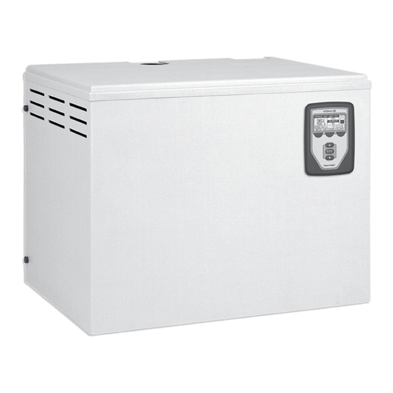
Familiarizing yourself with this manual will help ensure proper operation of the equipment for years to come. This manual covers the installation and maintenance procedures for both the HUMIDI-TECH and HUMIDI-TECH DI humidifiers. - Page 3 ® HUMIDI-TECH HUMIDIFIER Figure 3-1: HUMIDI-TECH humidifier The standard HUMIDI-TECH unit requires water conductivity of at least 100 µS/cm to operate. It will not Electrical operate with water treated connections by reverse osmosis or DN40 or DN50 flexible Condensate deionization processes.
-
Page 4: Electrical Specifications, Capacities And Dimensions
28.6 30.3 – SSR control: 1 kg All HUMIDI-TECHs operate at 50/60 VM-25 34.0 36.1 Hz. SDU-E is not an available option on 400V three-phase HUMIDI-TECH VM-30 40.9 43.3 models drawing more than 21.7 amps VM-34 46.3 49.1 and using SSR control. -
Page 5: Humidi-Tech Humidifier Overview
• Electrical and plumbing connections 6 mm diameter pilot holes using mounting template • Required clearances on the HUMIDI-TECH box. Secure frame to wall with • External water seal requirements coach screws provided. The mounting location should provide a minimum... -
Page 6: Piping
PIPING The final connection size is DN20 (3/4") for drain Water make up piping may be of any code- fitting and frame drain. This connection size should approved material (copper, steel, or plastic). The not be reduced. (See Figures below for proper drain final connection size is DN6 (1/4"). -
Page 7: Wiring
Power supply When selecting a space to install the HUMIDI-TECH, wiring must be rated for 105 °C. avoid areas close to sources of electromagnetic emissions such as power distribution transformers. -
Page 8: Dispersion Using Space Distribution Units (Sdu-E And Sdu-I)
VM-4 through VM-34. Mounting the SDU The SDU may be mounted on a wall above the HUMIDI-TECH cabinet or mounted on a wall remote from the HUMIDI-TECH. Use the mounting template on the box for correct placement. Two coach screws are provided with each fan unit. - Page 9 If the SDU-E or SDU-I is immediately above the HUMIDI-TECH, disconnect both hose clamps on the steam hose, grip the hose and rotate it to break it loose from the tubing, and then slide the hose up onto the SDU steam tube until sufficient clearance is provided to move the tank.
- Page 10 /h) and an airflow proving switch field wired to the (columns, beams, ceiling, pipes, etc.) before it HUMIDI-TECH humidifier electrical panel. A wiring disappears, it could collect and drip as water. The diagram of the SDU-E is included with the unit.
-
Page 11: Dispersion Using Dispersion Tubes
DN40 minimum hard pipe should be used instead. VM-30 and VM-34 must use a multiple tube steam dispersion system. Figure 11-2: Mounted horizontally in duct and lower than HUMIDI-TECH unit Table 11-1: Vapor hose sizing Capacity Vapor hose Model... -
Page 12: Dispersion Using A Rapid-Sorb Dispersion Panel
DISPERSION USING DISPERSION TUBES Figure 12-1: Single-Tube Mounting dispersion tube without condensate drain • Orient dispersion tubes so that tubelets point up. Insertion 65 mm • Connection can be made to the humidifier with length 85 mm vapor hose or hard piping. High temperature resin tubelets •... -
Page 13: Start-Up And Operation
Even though the HUMIDI-TECH has an internal 25 mm air gap, some local codes may require a vacuum breaker. Important: Minimum water supply pressure is 172 kPa. - Page 14 5. Confirm that the keypad is mounted on the diagram. HUMIDI-TECH with modular cable routed away from high voltage circuits and connected to the 12. During normal operation, the keypad will display J2 female connector on the control board.
-
Page 15: Maintenance
Safety first. determine your own unique maintenance schedule. • If the HUMIDI-TECH has an SDU mounted directly above it, the SDU cover must be Water quality makes a difference removed before removing the unit cover. - Page 16 MAINTENANCE ® Standard water models (HUMIDI-TECH Off-season shut-down procedure continued) 1. Switch off electrical power. 2. Loosen the four cover bolts and remove the 2. Remove enclosure. cover assembly from the tank. 3. Shut off water supply to make-up valve.
- Page 17 DI water models (HUMIDI-TECH 2. Loosen the four cover bolts and remove the cover assembly from the tank. The HUMIDI-TECH DI unit uses DI/RO water. Because these water types are mineral-free, 3. Inspect the tank interior for debris or pitting.
-
Page 18: Humidi-Tech (Standard Water Models)
® HUMIDI-TECH (STANDARD WATER )TROUBLE SHOOTING PROBLEM POSSIBLE CAUSE RECOMMENDED ACTION Humidifier does not heat. Incorrect or nonexistent supply Check main line safety switch. voltage to unit Check main line fuses. Check for proper supply voltage. Incorrect or nonexistent control Reset control transformer circuit breaker. -
Page 19: Humidi-Tech Di Trouble Shooting Guide
® HUMIDI-TECH DI TROUBLESHOOTING PROBLEM POSSIBLE CAUSE RECOMMENDED ACTION Control transformer Reset control transformer circuit breaker. Humidifier will not heat. Humidistat is not calling Set humidistat to call. Inspect for faulty humidistat. Safety controls open Check safety controls, airflow switch, high limit humidistat, etc. -
Page 20: Replacement Parts
REPLACEMENT PARTS ® HUMIDI-TECH 3/4" NPT frame drain standard water (male) model Tank drain Hole for fill tube Tank drain 3/4" NPT (male) HUMIDI-TECH DI model OM-778-1 Note: Refer to the tables on the next page for replacement part numbers. - Page 21 REPLACEMENT PARTS Table 21-1: HUMIDI-TECH ® replacement parts (refer to the drawing on previous page) Description Qty. Part No. Description Qty. Part No. Washer, #8 external tooth, pltd 700200-003 Head bolt, large Phillips, ¼ - 20 X 1" 700300-013 Nut, #8-32 hex, pltd...
- Page 22 REPLACEMENT PARTS Figure & Table 22-1: Space Distribution Unit (SDU-E) No. Description Qty. Part. No. Cabinet Base, SDU99 330000-003 Blower, SDU99 External Assembly 409540-003 Frame, SDU External 165542 Disp Chamber, SDU99 w/1 1/2" Out 160445-001 Disp Chamber, SDU99 w/2" Out 160445-002 Switch, Air Flow 406190...
- Page 23 REPLACEMENT PARTS Figure & Table 23-1: HUMIDI-TECH ® subpanel No. Description Qty. Part. No. with SCR Subpanel, VM99 Barrier 120801 Din Rail, 10.75" Long 167765-0107 Din Rail, 2.25 Long 167765-0022 Ground Lug, L-35 10-14 409250-017 GA CP-8 Ground Lug, L-70 6-8...
-
Page 24: Two-Year Limited Warranty
14949 Technology Drive • Eden Prairie, MN 55344 Phone: (800)328-4447 • (952) 949-2415 • Fax: (952) 949-2933 E-Mail: sales@dristeem.com • Web: www.dristeem.com Continuous product improvement is a policy of DRI-STEEM Humidifier Company therefore, product features and specifications are subject to change without notice.
Need help?
Do you have a question about the HUMIDI-TECH and is the answer not in the manual?
Questions and answers