ACTi CAM-6500 Series Hardware User Manual
Ip indoor high speed dome
Hide thumbs
Also See for CAM-6500 Series:
- Hardware user manual (75 pages) ,
- Quick installation manual (14 pages)
Table of Contents
Advertisement
Quick Links
Advertisement
Table of Contents

Subscribe to Our Youtube Channel
Related Manuals for ACTi CAM-6500 Series


Summary of Contents for ACTi CAM-6500 Series
- Page 1 IP Indoor High Speed Dome CAM-6500 series Ver. 070307 Hardware User’s Manual...
-
Page 2: Copyright
Copyright This manual is the intellectual property of ACTi and is protected by copyright. All rights are reserved. No part of this document maybe reproduced or transmitted for any purpose by any means including electronic or mechanical without the official written permission from ACTi. -
Page 3: Fcc/Ce Regulation
typographical or technical errors and reserve the right to make changes to the product and manuals without prior notice. FCC/CE Regulation NOTE: This equipment has been tested and found to comply with the limits for a Class A digital device, pursuant to Part 15 of the FCC Rules. These limits are designed to provide reasonable protection against harmful interference when the equipment is operated in a commercial environment. -
Page 4: Table Of Contents
Table of Contents PRECAUTIONS________________________________________________ 0-1 Copyright __________________________________________________________________ 0-1 Trademarks ________________________________________________________________ 0-1 Liability ___________________________________________________________________ 0-1 FCC/CE Regulation __________________________________________________________ 0-2 INTRODUCTION ________________________________________________1 Package Contents _________________________________________________ 1 Features and Benefits ______________________________________________ 2 Safety Instructions ________________________________________________ 5 Physical Description _______________________________________________ 7 Cable Wiring ____________________________________________________ 11 Cable Wiring and Connection ___________________________________________________11 Alarm Cable Wiring___________________________________________________________12 Mounting the IP High Speed Dome__________________________________ 13... - Page 5 B-1: OSD Display Format ______________________________________________________34 B-2: OSD Setup Menu _________________________________________________________34 B-3: Configuration Menu_______________________________________________________42 B-3-1 DEFAULT CAMERA __________________________________________________43 B-3-2 BACKLIGHT ________________________________________________________43 B-3-3 FOCUS _____________________________________________________________44 B-3-4 APERTURE _________________________________________________________45 B-3-5 AE MODE ___________________________________________________________45 B-3-6 WBC MODE _________________________________________________________47 B-3-7 ID DISPLAY _________________________________________________________48 B-3-8 SETUP MENU _______________________________________________________49 B-3-9 SETUP MENU2 (18x MODEL Only)______________________________________52 B-3-10...
-
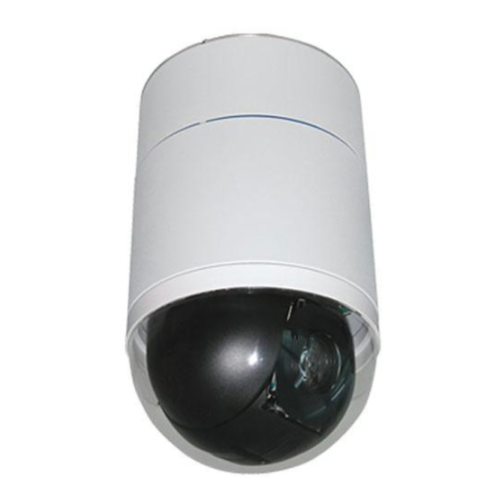
Page 6: Introduction
INTRODUCTION 1.1 Package Contents CAM-6500 series Warranty Card Product CD Power & A/V Cable LAN/WAN Cable Alarm Cable 5.4” Transparent Cover Decoration Ring / Fixing Plate Power Adaptor (Option) -
Page 7: Features And Benefits
1.2 Features and Benefits The IP High Speed Dome is designed to deliver superb performance and durability with an intelligent and stylish housing. It also provides a realiable real time images with outstanding image quality (D1, 720x480) at reasonable bandwidth through a standard TCP/IP network. That’s because it is Ethernet (LAN and WAN) ready and has a powerful ARM9 SoC and the MPEG-4 compression ASIC inside. - Page 8 MODEL) Low-Light Application Digital Slow Shutter and Electronic Shutter functions are provided for clear and high quality image. The minimum illumination is 0.01 Lux. Perfect Contrast Solution for High Image Quality Wide Dynamic Range function is a salient features incorporated to fit your needs (23x MODEL) Privacy Mask for Privacy Protection There is up to 24 privacy zones of camera view programmable.
- Page 9 The IP high speed dome provides two RJ-45 connectors. One is WAN and the other is LAN. The WAN port connects to the internet and LAN port connects to the local network. Since the internet’s bandwidth is very critical, the WAN port is equipped with a low latency PPPoE (Point-to-Point over Ethernet) which has excellent transmission speed and enables the IP high speed dome to connect to an ADSL or a cable modem.
-
Page 10: Safety Instructions
1.3 Safety Instructions Don’t use the power supply with other voltages This device is likely to be damaged or damage other equipments / personnel, if you use a power supply with different voltage than the one included with this device. All warranty of this product will be voided in the situations above. - Page 11 When the power-supply cord or plug is damaged. If liquid has been spilled, or objects have fallen into the video product. If the video product has been exposed to rain or water directly. If the video product does not operate normally by following the operating Instructions in this manual.
-
Page 12: Physical Description
1.4 Physical Description Indoor High Speed Dome Bottom Reset Button Step 1: Switch off IP device by disconnecting the power cable Step 2: Press and continue to hold the Reset Button. Reconnect the power cable while continuing to hold the reset button. Step 3: Keep holding the reset button depressed around 6 seconds, release the reset button. - Page 13 Pin 4 Line Lock Pin 5 System Initialization (for upgrade) Reserved Pin 6 RS-232 is reserved for internal use only; The Pin 3 and Pin 4, they are used for termination and Link Lock adjustment respectively. The Pin 5 is mainly used for return to factory default of camera setting.
- Page 14 Pelco P 9600 Select protocol: Pelco D, with switch no. 01 and baud rate 2400, for instance, the ID switch should be set as below: decimal single digit 16 Pin Connector for LAN/WAN The LAN/WAN cable (shown as the figure below) is shipped with IP high speed dome.
- Page 15 11~20 Alarm Pin (Not wired) VGND 24AWG Video NOTE: For alarm connection, please refer to section 1.5 Cable Wiring. Power Input Wiring Indication PIN NAME DESCRIPTION of Power Adapter AC24V AC 24V of Power Input Brown E-GND E-Ground Pin of Power Input Green/Yellow AC24V AC 24V of Power Input Blue...
-
Page 16: Cable Wiring
1.5 Cable Wiring Cable Wiring and Connection Users may need to do cable wiring when connecting alarm input and output devices. The table follows will illustrate the way to wire cords into the connector housing (shown in the figures below). Insert the terminal into the pin holes on the connector housing, with the hook... -
Page 17: Alarm Cable Wiring
Alarm Cable Wiring The alarm pins are serviceable for connecting alarm input and output devices, such as alarm sensors, sirens or flashing lights with the surveillance system. The table shown as follows lists the definition of alarm pins on the 22-pin connector. Definition ALM NC ALM NO... -
Page 18: Mounting The Ip High Speed Dome
1.6 Mounting the IP High Speed Dome Generally, there are three kinds of ceiling mounting methods: surface mount, in-ceiling mount, and mounting with straight tube. The surface mounting kit is shipped with IP high speed dome. For more detailed information, please refer to Appendix A. -
Page 19: Basic Connections
1.7 Basic Connections Follow the procedures below to connect the IP high speed dome to the respective apparatuses. -
Page 20: Appendix A: Speed Dome Installation
Appendix A: Speed Dome Installation Basing on user’s installation environments, the dome can be installed on ceiling, on wall or on pole. In the following section, various indoor speed dome installation accessories, installation methods and installation procedures will be described in detail. - Page 21 Transparent Cover/Smoke Cover Diameter: 137 mm (5.4 inches); 127 mm (5.0 inches) 5’’ Transparent Cover 5.4’’ Transparent Cover 5’’ Smoke Cover 5.4’’ Smoke Cover Indoor Mount Kit White; Diameter: 140 mm (5.5 inches); Height: 74 mm (2.9 inches) For mounting indoor dome camera onto a gooseneck/straight tube. Mounting Accessories...
- Page 22 Gooseneck Tube White; 298×385 mm (11.73×15.56 inches) ; 2.1 kg (4.6 lbs) Supplied with rubber washer-8×1, pendant tube washer×1, spring washer-8×1 and waterproof rubber×1, M8*12 screw×1. Straight Tube White; Height: 250/500 mm (9.8/19.7 inches); Diameter: 50 mm (2 inches) 1 kg (2.2 lbs) / 1.8 kg (4 lbs). Supplied with rubber washer-8×1, pendant tube washer×1, spring washer-8×1 and waterproof rubber×1, M8*12 screw×1.
- Page 23 Pole Thin Direct Mounting White; 232(L)×136(W)×60(D) mm (9.1×5.4×2.4 inches); Diameter: 112~140 mm (4.4~5.5 inches); 0.7 kg (1.6 lbs). Supplied with stainless steel straps×4, M8*16 screw×4, washer×4. Corner Thin Box White, 300(L)×164(W)×222(D) mm (11.8×6.5×8.7 inches); 3 kg (6.7 lbs); Supplied with washer×4, M8*16 screw×4 and spring washer×4.
- Page 24 Pole Thin Box White; 291(L)×136(W)×245(D) mm (11.5×5.3×9.5 inches); 3.1 kg (6.9 lbs); Supplied with M8*16 screw×4, washer×4, spring washer×4, stainless steel straps×4. Wall Box Mounting White, 270(L)×166(W)×95(D) (10.6×6.5×3.7 inches); 2.2 kg (4.84 lbs); Supplied with M8*16 screw×4, washer×4, spring washer×4...
- Page 25 Stainless Steel Straps For fixing Pole Direct Mounting/ Pole Box on the pole. Width: 0.63”; 0.02 kg (0.04 lbs) Stainless Strap Cutter For tension, cut and crimp stainless steel straps. 1.4 kg (3.1 lbs) Suitable for straps width: 1/2”, 5/8”, 3/4” Other Application Accessories Power Box White;...
-
Page 26: A-2: Ceiling Mount
A-2: Ceiling Mount Generally, there are three kinds of speed dome camera ceiling mounting methods: surface mount, in-ceiling mount, and mounting with straight tube. Refer to the following sections for more detailed information. The following figures show how cables connect to the speed dome camera in different ways. -
Page 27: A-3: Surface Ceiling Mounting
A-3: Surface Ceiling Mounting Surface Ceiling Mounting is a standard installation for an indoor dome, and general mounting accessories are equipped in the standard indoor dome camera package. Here lists the items and tools needed to mount the dome camera onto the ceilings. The supplied items are all in the speed dome camera package. - Page 28 STEP 3 Attach the Mount to the ceiling. Mark the locations where all three ceiling holes should go. STEP 4 Drill these holes on the surface ceiling. STEP 5 Fix the Mount to the holes on the surface ceiling with three screws.
-
Page 29: A-4: In-Ceiling Mounting
STEP 7 Attach the dome body to the Mount and rotate the dome clockwise. Tighten the fixing screw to fix the dome body. STEP 8 Fix the decoration ring to the bracket and then place the optical cover. A-4: In-ceiling Mounting Here lists the items and tools needed to mount the dome camera into the ceilings. - Page 30 mount accessory for in-ceiling mounting. Step 1: Disassemble the wing (indicated in the diagram) from the T-Bar Ceiling Mount, and take out the supplied screw in the small bag. Step 2: Attach the separated wing to the dome, as shown in the diagram.
- Page 31 STEP 4 Put up the T-Bar into the ceiling hole. STEP 5 Rotate T-Bar wings of the hinge to fix the T-Bar at the edge of the ceiling hole. STEP 6 Tighten the screws, and the T-Bar wings will adhere to the ceiling.
-
Page 32: A-5: Ceiling Mount With Straight Tube
STEP 8 Mount the dome body to the Bracket and rotate it clockwise. Tighten the fixing screw to fix the dome body. STEP 9 Fix the decoration ring to the bracket and then place the optical cover. A-5: Ceiling Mount with Straight Tube The straight tube is available in different length: 25cm and 50cm. -
Page 33: A-6: Wall Mount
A-6: Wall Mount A-6-1 Wall Mounting with Gooseneck Tble The following figures show how cables run through the tube in different ways. Cables exposed Cables recessed Follow the steps to mount the speed dome with the gooseneck tube. (1) Make a cable entry hole on the wall to recess the cables. Otherwise,... -
Page 34: A-6-2 Wall Box Mounting
cables can be threaded through the cable entry hole on the tube. (2) Fix the suspension bracket on the wall (3) Thread the cables through the gooseneck tube and the Indoor Mount kit and connect them to the dome camera. (4) Fix the Indoor Mount kit to the goosenect tube using the equipped screqs and washers. -
Page 35: A-7: Corner Mount
A-7: Corner Mount A-7-1 Corner Standard Mounting Plate With the corner mounting plate and gooseneck, the dome can be mounted on wall. There are various types of corner mounting accessories with different width. Make a cable entry hole on the wall to recess the cables. Otherwise, cables can be threaded through the cable entry hole on the tube Fix the suspension bracket on the wall Attache the gooseneck tube to the firmly fixed bracket... -
Page 36: A-7-2 Corner Thin/Wide Box Mounting
A-7-2 Corner Thin/Wide Box Mounting The thin/wide corner box is designed to be installed with a gooseneck tube. Follow the steps to mount the dome camera with the corner box and gooseneck tube. Make a cable entry hole on the wall to recess the cables. Otherwise, cables can be threaded through the cable entry hole on the tube Fix the suspension bracket on the wall Attache the gooseneck tube to the firmly fixed bracket... -
Page 37: A-8: Pole Mount
A-8: Pole Mount A-8-1 Pole Thin/Wide Direct Mounting The dome can be installed on a pole with a thin or wide pole mounting accessory and a gooseneck. Fasten the suspension mounting plate on a pole with equipped stainless straps Fix the gooseneck tube on the pole mounting plate Thread the cables through the gooseneck tube and the Indoor Mount kit and connect them to the speed dome camera Fix the Indoor Mount kit to the gooseneck tube using the screws and washers. -
Page 38: A-8-2 Pole Thin/Wide Box Mounting
A-8-2 Pole Thin/Wide Box Mounting Follow the steps to mount the PTZ camera with the pole box and gooseneck tube. Fasten the pole box on a pole with equipped stainless straps Fix the gooseneck tube to the pole box Thread the cables through the gooseneck tube and the top holder and connect them to the PTZ camera Fix the top holder to the gooseneck tube using the screws and washers. -
Page 39: Appendix B: Osd Menu Notes
Appendix B: OSD Menu Notes B-1: OSD Display Format The information shown on the screen are described in terms of OSD display, position and function description in the table below. Position Function OSD Display Description Auto Focus Mode Focus Modes Manual Focus Mode Back Light Compensation OFF Backlight... - Page 40 Item Layer 1 Layer 2 Layer 3 Default CAMERA BACKLIGHT <ON>, <OFF> AUTO AF Mode <Normal>, <Interval>, <Zoom Normal FOCUS Trigger> MANUAL Focus Manual Speed <01>~<08> AUTO Exposure Comp. <OFF>, <1>~<15> BRIGHT Bright <0> ~ <31> AE MODE SHUTTER Shutter Speed <1> ~ <1/10000> Sec. GAIN Gain <-3>...
- Page 41 Item Layer 1 Layer 2 Layer 3 Default SETTNG ALARM SWITCH <ON>, <OFF> ALARM TYPE <N.O.> (Normal Open), <N.C.> (Normal N.C. Close) ☆ ALARM ACTION PRESET SEQUENCE AUTOPAN CRUISE PRESET POINT <001> ~ <256> SEQUENCE LINE <1> ~ <8> AUTOPAN LINE <1>...
- Page 42 Item Layer 1 Layer 2 Layer 3 Default END POINT <TO FIND>, <TO SAVE> DIRECTION <RIGHT>, <LEFT> Right SPEED <01> ~ <04> RUN AUTOPAN EXIT RECORD START RECORD END CRUISE RUN CRUISE EXIT IR FUNCTION (F/U model <AUTO>, <ON> Auto only) DETECT SWITCH <ON>, <OFF>...
- Page 43 Item Layer 1 Layer 2 Layer 3 Default SCHEDULE SW. <ON>, <OFF> SCHEDULE <01> ~ <32> POINT SCHEDULE HOUR SCHEDULE MIN ☆ SCHEDULE NONE MODE PRESET SEQUENCE AUTOPAN SCHEDULE CRUISE IR FUNC. NO FUNCTION PRESET POINT <1> ~ <256> SEQUENCE LINE <1>...
- Page 44 Item Layer 1 Layer 2 Layer 3 Default MANUAL H APERTURE <00> ~ <31> V APERTURE <00> ~ <31> AUTO IRIS OFFSET <00> ~ <99> SHUTTER SHUTTER SPEED <1/2> ~ AE MODE <1/30000> IRIS IRIS <00> ~ <09> AGC <00> ~ <05> ☆...
- Page 45 Item Layer 1 Layer 2 Layer 3 Default PRESET POINT <001> ~ <256> SEQUENCE LINE <1> ~ <8> AUTOPAN LINE <1> ~ <4> CRUISE LINE <1> DWELL TIME <001> ~ <127> Sec., ALWAYS ALWAYS EXIT HOME FUNC. <ON>, <OFF> ☆ SELECT MODE PRESET SEQUENCE...
- Page 46 Item Layer 1 Layer 2 Layer 3 Default RUN CRUISE EXIT AUTO THRESHOLD <LOW>, <MID>, <HI> IR FUNCTION IR COLOR <B/W>, <COLOR> (K model only) EXIT WDR SWITCH <ON>, <OFF> ☆ WDR FUNCTION AUTO MANUA RATIO LEVEL <000>~<128> SETTING SHUTTER LEVEL (K model only) <000>~<128>...
-
Page 47: B-3: Configuration Menu
Item Layer 1 Layer 2 Layer 3 Default SWITCH SCHEDULE <01> ~ <32> POINT SCHEDULE HOUR SCHEDULE MIN ☆ SCHEDULE NONE MODE PRESET SEQUENCE AUTOPAN CRUISE IR FUNC. NO FUNCTION PRESET <1> ~ <256> SEQUENCE LINE <1> ~ <8> AUTOPAN LINE <1>... -
Page 48: Default Camera
18x MODEL 22x MODEL/23x MODEL MAIN PAGE 1 MAIN PAGE 1 DEFAULT CAMERA DEFAULT CAMERA BACKLIGHT BACKLIGHT FOCUS AUTO FOCUS AUTO AE MODE AUTO APERTURE AUTO WBC MODE AUTO AE MODE AUTO ID DISPLAY WBC MODE AUTO SETUP MENU1 ID DISPLAY SETUP MENU2 SETUP MENU ENTER... -
Page 49: B-3-3 Focus
B-3-3 FOCUS Automatically adjusts the focus position to maximize the high frequency content of the picture in a center measurement area, taking into consideration the high luminance and strong contrast components. The focus of the dome camera can be operated in two modes: Manual Focus mode and Auto Focus mode. Different settings for various models are described as follows. -
Page 50: B-3-4 Aperture
B-3-4 APERTURE Sharpness is the subjective evaluation of detail in the picture. With this “APEATURE” function, users can adjust the enhancement of the edges of objects in the picture. When shooting text, this function may help by making them sharper and achieve a better image. - Page 51 internal brightness reference level through auto Exposure Comp. to control the brightness of camera. The value of Exposure Comp. is selectable from <0> to <16> and the gain varies from -10.5 dB to 10.5 dB. Each step is 1.5 dB; the Exposure Comp. vaue <7> is equal to gain value 0 dB. The camera will not compensate brightness when the Exposure Comp.
-
Page 52: Wbc Mode
to get consistent exposure. ♦ IRIS With this option, the IRIS priority is higher than SHUTTER and AGC; SHUTTER and AGC circuit will function automatically in cooperating with IRIS to get consistent exposure. If the IRIS is modified manually, the action of exposure compensation depends on the AGC circuit. -
Page 53: Id Display
3200K Base mode ♦ OUTDOOR 5800K Base mode ♦ Auto Tracing White Balance mode. The dome taking out the signals in a screen in the range from 2000K to 10000K. ♦ MANUAL In this mode, users can change the White Balance value manually; R gain and B gain are adjustable and range from 0 to 128. -
Page 54: Setup Menu
monitor screen. ♦ Hide the ID address of the selected dome. B-3-8 SETUP MENU Users can adjust camera lens model parameters under SETUP MENUs. Depending on the model of dome cameras, the SETUP MENUs are different. 18x MODEL SETUP MENU1 SETUP MENU2 FLIP ENTER... - Page 55 User can track an object continuously when it passes through under dome camera with setting Flip to IMAGE (digital flip) or M.E. (mechanical flip). FLIP SETTING FLIP EXIT IMAGE IMAGE represents digital IMAGE FLIP, enables users to keep tracking object seamlessly and no delay occurs in comparing with mechanical flip. NOTE: The Privacy Mask function will be automatically disabled if the Image Flip function is enabled, and “Masking...
- Page 56 algorithm when zooming automatically. The larger zoom ratio leads the lower rotation speed. ♦ AUTO CALIBRATION There are one horizontal and one vertical infrared rays check points in each dome. When the dome camera position may be moved during installation or maintenance, the relative distance between the original set point and the check point has been changed.
-
Page 57: B-3-9 Setup Menu2 (18X Model Only)
lux. 23x MODEL The shutter speed is adjustable on 23x MODEL. With the slowest shutter speed, users can see objects in a dark environment under 0.2 lux; or see a smooth video image with a higher shutter speed. The options are from <1/2> to <1/60>. -
Page 58: B-3-10 Title Display
SETUP MENU2 APERTURE MASK DISPLAY FIRST ♦ APERTURE Under this setup menu, users can adjust the enhancement of the edges of objects in the picture. There are 16 levels of adjustment; the options are <01) ~ <16>, <01> represents “no enhancement”. When shooting text, this function may help by making them sharper. -
Page 59: B-3-11 Title Setting
♦ When the TITLE DISPLAY is set <OFF>, no title will be displayed on the screen even titles are set in advance. B-3-11 TITLE SETTING Up to 16 zone titles can be set with maximum 20 characters for each title; two mask zones are allowed to set in a view area. -
Page 60: B-3-12 Alarm Setting
B-3-12 ALARM SETTING The integrated high speed dome provides eight alarm inputs and two alarm outputs (N.O. and N.C.) to connect alarm devices. With this function, dome will cooperates with alarm system to catch the event images. For wiring, please refer to the installation guide and/or qualified service personnel. -
Page 61: B-3-13 Home Setting
♦ ALARM ACTION Select one of these modes that choose a kind of actions that should be executed when an alarm is triggered. The alarm actions can be set to execute the preset position, sequence, auto-pan or cruise function. ♦ PRESET Select a preset point where the dome should go when an alarm pin is triggered. - Page 62 is the HOME function. HOME function allows constant and accurate monitoring, to avoid the speed dome stops or missing events. HOME SETTING HOME FUNCTION SELECT MODE PRESET PRESET POINT RETURN TIME ENTER EXIT ♦ HOME FUNCTION The item is used to enable or disable the HOME function. ♦...
-
Page 63: B-3-14 Seqence
♦ If HOME function is enabled, the users are allowed to execute HOME function manually by selecting this item. ♦ EXIT Exit the HOME SETTING menu. B-3-14 SEQENCE The function executes pre-positioning of the pan, tilt, zoom and focus features in a certain sequence for a camera. -
Page 64: B-3-15 Autopan
setup speed range is from 1 ~ 15. Refer to below table for more information. PAN (degree/sec.) TILT (degree/sec.) Speed 1 Speed 2 Speed 3 Speed 4 Speed 5 Speed 6 Speed 7 Speed 8 Speed 9 Speed 10 Speed 11 Speed 12 Speed 13 Speed 14... - Page 65 AUTOPAN AUTOPAN LINE START POINT TO FIND END POINT TO FIND DIRECTION RIGHT SPEED RUN AUTOPAN ENTER EXIT ♦ AUTOPAN LINE There are four sets of auto-pan lines built in speed dome camera. Users are able to command the speed dome camera to do continuously panning without limit by setting the start point the same as endpoint.
-
Page 66: B-3-16 Cruise
♦ SPEED The item is for defining the speed dome camera rotation speed while running auto-pan. The speed is adjustable from 1 to 4; refer to the table below for details. PAN (degree/sec.) Speed 1 Speed 2 Speed 3 Speed 4 ♦... -
Page 67: B-3-17 Ir Function (Removable Ir Cut)
♦ RECORD START Follow the description to record the CRUISE path. 1. Rotate the speed dome camera to a desired view area. The percentage of the memory buffer will be displayed on the screen. 2. Pan, tilt the dome camera to form a path. The zoom setting is only available with 18x MODEL. -
Page 68: B-3-18 Alarm Detect (18X Model Only)
♦ Select the item to remove the IR cut filter. 23x MODEL IR FUNCTION THRESHOLD IR COLOR COLOR EXIT ♦ AUTO The internal circuit will automatically decide the occasion to remove the IR cut filter according to the image brightness level. THRESHOLD The speed dome will remove the filter immediately when the threshold value is reached. -
Page 69: B-3-19 Wdr Setting (23X Model Only)
♦ DETECT MODE Four alarm detect modes are provided for different application. INT. FOCUS The alarm will be triggered if the internal focus changes; and if the focus returns to the original position, the alarm will stop. FIX FOCUS If focus movement is detected, the alarm will be triggered, and the alarm stops when focus returns to the original position. -
Page 70: B-3-20 Privacy
WDR SETTING WDR SWITCH WDR FUNCTION AUTO EXIT ♦ WDR SWITCH Enable or disable the WDR function with the item. ♦ WDR FUNCTION The item is used to define the WDR function mode. AUTO If select <AUTO>, the speed dome camera operates the WDR function automatically. - Page 71 18x MODEL PRIVACY MASK MENU PRIVACY SWITCH TRANSPARENCY COLOR BLACK SET MASK EXIT ♦ PRIVACY SWITCH User can enable or disable the Privacy Mask function through this item. ♦ TRANSPARENCY The colour of privacy mask can be set as transparent related to background image.
- Page 72 H SIZE (00 ~ 80) User can adjust the horizontal size of privacy mask through this item. Set the H and V size to 0 can also delete the selected mask. V SIZE (00 ~ 60) User can adjust the vertical size of privacy mask through this item. Set the H and V size to 0 can also delete the selected mask.
- Page 73 H CENTER(000 ~ 256) The original center of mask zone is the center of screen. User can move the center of mask zone to another position through adjust this value. V CENTER(000 ~ 256) The original center of mask zone is the center of screen. User can move the center of mask zone to another position through adjust this value.
-
Page 74: B-3-21 Time Function
B-3-21 TIME FUNCTION The item is used to set the TIME related parameters of the integrated high speed dome. TIME SETTING TIME DISPLAY SET YEAR SET MONTH SET DAY SET HOUR SET MINUTE EXIT+SAVE ♦ TIME DISPLAY Select <ON> to display the Time information on screen, or <NO> not to display. -
Page 75: B-3-23 Exit Osd
♦ SCHEDULE SWITCH Select <ON> to enable the Schedule function or <OFF> to disable. ♦ SCHEDULE POINT Users are allowed to set up 32 schedule points. ♦ SCHEDULE HOUR / MINUTE The items are for setting up the time of schedule points. ♦...
Need help?
Do you have a question about the CAM-6500 Series and is the answer not in the manual?
Questions and answers