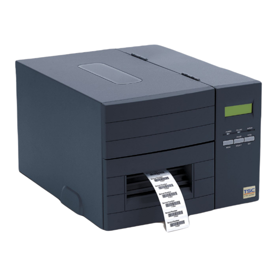
TSC TTP-244M Pro User Manual
Thermal transfer / direct thermal bar code printer
Hide thumbs
Also See for TTP-244M Pro:
- Service manual (54 pages) ,
- Programming manual (252 pages) ,
- Programming manual (434 pages)

Related Manuals for TSC TTP-244M Pro


Summary of Contents for TSC TTP-244M Pro
- Page 1 TTP-244M Pro / TTP-342M Pro TTP-244ME Pro / TTP-342ME Pro THERMAL TRANSFER / DIRECT THERMAL BAR CODE PRINTER USER’S MANUAL...
- Page 2 Information in this document is subject to change without notice and does not represent a commitment on the part of TSC Auto ID Technology Co. No part of this manual may be reproduced or transmitted in any form or by any means, for any purpose other than the purchaser’s personal use, without the expressed...
-
Page 3: Table Of Contents
CONTENTS 1. PRODUCT INTRODUCTION.............. 1 2. GETTING STARTED ................2 2.1 Equipment Checklist ..................2 2.2 Printer Parts ..................... 3 2.3 Buttons and Indicators ..................6 3. SET UP ....................8 3.1 Setting up the Printer ..................8 3.2 Loading the Ribbon ..................9 3.3 Loading the Label .................. -
Page 4: Product Introduction
PRODUCT INTRODUCTION Thank you very much for purchasing this bar code printer. The attractive printer delivers superior performance at an economical price. Both powerful and easy- to-use, this printer is your best choice. The printer offers both thermal transfer and direct thermal printing at user selectable speeds: either 1.5, 2.0, 3.0 and 4.0 IPS (Inch Per Second) for 203 DPI model;... -
Page 5: Getting Started
GETTING STARTED This printer has been specially packaged to withstand damage in the shipping process. However, for fear that unexpected damage might occur, upon receiving the bar code printer, carefully inspect the package and the device. In case of evident damage, contact the carrier directly to specify the nature and extent of the damage. -
Page 6: Printer Parts
2.2 Printer Parts Front View 1. Printer cover/ Release handle 2. Label dispense opening 3. Liner opening (Option function) 4. MENU button (Option for E series) 5. PAUSE/ SELECT button 6. FEED/ SET button 7. Error indicator 8. On-line indicator 9. - Page 7 Interior View 1. Ribbon supply spindle 2. Label roll guard 3. Label supply spindle 4. Ribbon rewind spindle 5. Sensor switch 6. Print head release lever 7. Front panel 8. Printer cover 9. Print head 10. Platen roller 11. Media sensor 12.
- Page 8 Rear View 1. Centronics interface (Option for E series) 2. Ethernet interface (Option) 3. USB interface 4. Label insert opening (For use with external labels) 5. RS-232C interface connector 6. SD card socket 7. Power switch 8. Power cord socket Note: The interface picture here is for reference only.
-
Page 9: Buttons And Indicators
2.3 Buttons and Indicators POWER Indicator The green POWER indicator illuminates when the power switch is turned on. ON-LINE Indicator The green ON-LINE indicator illuminates when the printer is ready to print. When the PAUSE button is pressed, the ON-LINE indicator will be flash. ERROR Indicator (Error/Paper Empty) The red ERROR indicator illuminates in the event of a printer error, such as paper empty, ribbon empty, out of memory, and so forth. - Page 10 The SELECT button allows the user select for the sub-item to be processed. Once the sub-item has been selected, the user can change its setting by pressing the SET button. (Option function for E series) FEED/SET Button As does the PAUSE/SELECT button, this button also has dual functions: FEED and SET.
-
Page 11: Set Up
3. SET UP 3.1 Setting up the Printer 1. Place the printer on a flat, secure surface. 2. Make sure the power switch is off. 3. Connect the printer to the computer mainframe with the provided printer cable. 4. Plug the power cord into the AC power cord socket at the rear of the printer, and then plug the power cord into a properly grounded receptable. -
Page 12: Loading The Ribbon
3.2 Loading the Ribbon 1. Open the printer cover and front panel. 2. Place an empty paper core onto the ribbon rewind spindle. 3. Insert the left side first. Mount the ribbon rewind paper core on the front hubs. Please be noted that the bigger hub side with 4 ribs must be installed toward the right side of ribbon mechanism. - Page 13 4. Install a ribbon on the ribbon supply spindle. Mount the ribbon supply spindle on the rear hubs. Insert the left side first. 5. Please be noted that the bigger hub side with 4 ribs must be installed toward the right side of ribbon mechanism. 6.
- Page 14 7. Following the direction of the RIBBON label, pull the ribbon leader to the front from beneath the printer carriage. 8. Attach the ribbon leader to the ribbon rewind paper core (with a tape). 5. Rotate the ribbon rewind roller until the ribbon overlaps the ribbon leader and stretches tight.
- Page 15 To use direct thermal mode, install the label and engage the ribbon mechanism before switching on the printer. Please refer to videos on TSC YouTube or driver CD.
-
Page 16: Loading The Label
3.3 Loading the Label 1. Open the printer cover and front panel. 2. Lower the label roll guard to the horizontal position, slide the label stock into label roll spindle, and then flip back the label roll guard. 3. Disengage the printer carriage by pulling the print head release lever located to the left side of the platen. - Page 17 4. Install the label so that it goes (when using an external label roll mount: through the label feed slot) in the direction of the LABEL label and under the ribbon mechanism to lay upon the platen. 5. Adjust the label guide to fit the width of the media. 6.
- Page 18 ERROR LED will flash. Reload the ribbon or media without turning off the printer. Press the FEED button a few times until the ON- LINE LED illuminates, the printing job will be resumed without data loss. Please refer to videos on TSC YouTube or driver CD.
-
Page 19: Loading Media In Peel-Off Mode (Option)
3.4 Loading Media in Peel-off Mode (Option) 1. Please refer to section 3.3 to loarding the media and to calibrate the sensor first. 2. Remove the foremost one or two labels from the liner. Liner Label 3. Pull the print head release lever to feed the liner between the platen and the white peel-off roller. - Page 20 Liner opening 5. Close the print head, front panel and printer cover. Liner 6. Set the “post-print action” to “peel”. Peeling will automatically start. Press the FEED button to test. Label Liner Note: Please calibrate the gap/black mark sensor when changing media.
-
Page 21: Loading Media In Cutter Mode (Option)
3.5 Loading Media in Cutter Mode (Option) 1. Please refer to section 3.3 to loarding the media. 2. Install the label so that it goes (when using an external label roll mount: through the label feed slot) in the direction of the LABEL label and under the ribbon mechanism. -
Page 22: Power-On Utilities
4. POWER-ON UTILITIES There are three power-on utilities to set up and test the printer hardware. These utilities are activated by pressing the FEED or PAUSE button and turning on the printer power simultaneously. The utilities are listed below: 1. Self test 2. - Page 23 Self-test printout (with printer firmware V7.0 and later version) Model name F/W version Firmware checksum Printer S/N TSC configuration file System date System time Printed mileage (meter) Cutting counter Print speed (inch/sec) Print darkness Label size (inch) Gap distance (inch)
- Page 24 Numbers of download files Total & available memory space Print head check pattern When the self test is completed, the printer enters the dump mode. Please turn the printer's power off and then on again to resume normal printing. Note: The physical flash memory on board is 4MB respectively.
-
Page 25: Gap Sensor Calibration Utility
4.2 Gap Sensor Calibration Utility This utility is used to calibrate the sensitivity of the gap sensor. Users may have to calibrate the gap sensor on two occasions: 1. Changing to a new type of label media. 2. Initializing the printer. Note: The ERROR LED may flash if gap sensor is not calibrated properly. -
Page 26: Printer Initialization
4.3 Printer Initialization Printer initialization clears all downloaded files resident in the flash memory and sets printer parameters to default values. Please follow the steps below to initialize the printer: 1. Turn off the printer power. 2. Hold down the PAUSE and FEED buttons and turn on the printer power. 3. -
Page 27: Diagnostic Tool
5. DIAGNOSTIC TOOL TSC’s Diagnostic Utility is an integrated tool incorporating features that enable you to explore a printer’s settings/status; change a printer’s settings; download graphics, fonts and firmware; create a printer bitmap font; and send additional commands to a printer. With the aid of this powerful tool, you can review printer status and settings in an instant, which makes it much easier to troubleshoot problems and other issues. -
Page 28: Printer Function
5.2 Printer Function 1. Select the PC interface connected with bar code printer. 2. Click the “Function” button to setting. 3. The detail functions in the Printer Function Group are listed as below. Function Description Calibrate the sensor specified in the Printer Calibrate Sensor Setup group media sensor field Setup the IP address, subnet mask, gateway... -
Page 29: Troubleshooting
6. TROUBLESHOOTING The following guide lists some of the most common problems that may be encountered when operating the bar code printer. If the printer still does not function after all suggested solutions have been invoked, please contact the Customer Service Department of your purchased reseller or distributor for assistance Problem Solution... -
Page 30: Maintenance
7. MAINTENANCE This session presents the clean tools and methods to maintain your printer. 1. Please use one of following material to clean the printer. Cotton swab (Head cleaner pen) Lint-free cloth Vacuum / Blower brush 100% ethanol 2. -
Page 31: Revise History
Revise History Date Content Editor Camille 2013/3/21 Modify section 4.1 Add cutter module specification on section 3.5 Camille 2013/4/3 Add V7.0 F/W self test on section 4.1 Add TSC YouTube web address... -
Page 32: Appendix A Menu Control Flowchart (Option)
Appendix A Menu Control Flowchart (Option) The following shows the control flowchart of the menu. READY PRINTER INFO.: PRINTER INFO.: PRINTER INFO.: PRINTER INFO.: PRINTER INFO.: PRINTER INFO.: TTP243M V1.XX SPEED:3 DENSITY:8 COM1:96,N,8,1 CODE PAGE:437 COUNTRY:001 PRINTER INFO.: PRINTER INFO.: PRINTER INFO.: PRINTER INFO.: PRINTER INFO.:... - Page 33 PRINTER SETUP: PRINTER SETUP: PRINTER SETUP: PRINTER SETUP: READY LANG:ENG LANG:繁體中文 LANG:日本語 LANG:簡体中文 PRINTER SETUP: PRINTER SETUP: PRINTER SETUP: MENU SPEED:1.5 SPEED:2 SPEED:3 SELECT PRINTER SETUP: PRINTER SETUP: ..PRINTER SETUP: DENSITY:0 DENSITY:1 DENSITY:15 PRINTER SETUP: PRINTER SETUP: PRINTER SETUP: PRINTER SETUP: BAUD RATE:19200 BAUD RATE:9600...
- Page 34 PRINTER SETUP: PRINTER SETUP: READY DATA BITS:8 DATA BITS:7 MENU PRINTER SETUP: PRINTER SETUP: STOP BITS:1 STOP BITS:2 SELECT PRINTER SETUP: LANG:ENG...
- Page 35 9F., No.95, Minquan Rd., Xindian Dist., No.35, Sec. 2, Ligong 1st Rd., Wujie Township, New Taipei City 23141, Taiwan (R.O.C.) Yilan County 26841, Taiwan (R.O.C.) TEL: +886-2-2218-6789 TEL: +886-3-990-6677 FAX: +886-2-2218-5678 FAX: +886-3-990-5577 Web site: www.tscprinters.com E-mail: printer_sales@tscprinters.com TSC Auto ID Technology Co., Ltd. tech_support@tscprinters.com...
Need help?
Do you have a question about the TTP-244M Pro and is the answer not in the manual?
Questions and answers