
Related Manuals for Electrolux T5675


Summary of Contents for Electrolux T5675
-
Page 1: Tumble Dryer
Service Manual Tumble dryer T5675 Type N2... 438 9038-20/EN 2014.03.12 Original instructions... -
Page 3: Table Of Contents
Contents Contents 1 Symbols ..........................5 2 Technical data ........................6 2.1 Drawing ........................6 2.2 Technical data....................... 7 2.3 Connections........................7 2.4 Sound levels ......................... 7 3 Machine presentation......................8 4 Function check ........................9 5 Sensors and overheating thermostats ................11 5.1 Inlet air.........................11 5.1.1 Overheating thermostat ..................11 5.1.2 Heating sensor (PT100).................. - Page 4 Contents 12.1.1 Description ......................93 12.1.2 Connections ...................... 94 12.1.3 Replacement of control system CPU ..............95 12.2 Control knob ......................99 12.2.1 Replacement of control knob ................99 13 Coin meter........................102 13.1 Replacement of coin meter..................102 14 I/O modules........................103 14.1 General........................
-
Page 5: Symbols
Symbols 1 Symbols Caution Caution, hot surface Read the instructions before using the machine... -
Page 6: Technical Data
Technical data 2 Technical data 2.1 Drawing B(b) B(a) Operating panel Door opening, ⌀ 810 mm Electrical connection Gas connection Exhaust connection Steam: in Steam: out B(a) B(b) 1560 1640 1857 1490 1560... -
Page 7: Technical Data
Technical data 2.2 Technical data Weight, net Drum volume litres Drum diameter Drum depth Drum speed, medium load Rated capacity, filling factor 1:18 (Max. load) 37.5 Rated capacity, filling factor 1:22 (Recommended load) 30.6 Heating: Electricity Heating: Gas Heating: Steam Maximum air flow, Electric 50 Hz / 60 Hz 1140 / 1140 Maximum air flow, Gas 50 Hz / 60 Hz... -
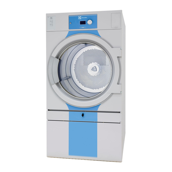
Page 8: Machine Presentation
Machine presentation 3 Machine presentation fig.W00268 ① Sensors and overheating thermostats Door Motor Heating unit Drum Control panel with Control system I/O modules After a repair has been made Whenever a repair has been made, a function check must be performed before the machine can be used again. -
Page 9: Function Check
Function check 4 Function check May only be carried out by qualified personnel. A function check must be made when the installation is finished and before the machine can be ready to be used. Whenever a repair has been made, a function check must be performed before the machine can be used again. - Page 10 Function check If the direction is wrong, swop two of the three phases to the left on the connection terminal. ③ fig.7119 Check the heat • Let the machine work for five minutes on a program with heat. • Check that the heating is working by opening the door and feel if there is heat in the drum. Ready to use If all tests are OK the machine is now ready to be used.
-
Page 11: Sensors And Overheating Thermostats
Sensors and overheating thermostats 5 Sensors and overheating thermostats 5.1 Inlet air 5.1.1 Overheating thermostat Description The inlet overheating thermostat is placed on the heating module on the back of the machine. The inlet overheating thermostat opens in the event of overheating and shuts off the machine. Resetting Disconnect the power to the machine. -
Page 12: Heating Sensor (Pt100)
Sensors and overheating thermostats 5.1.2 Heating sensor (PT100) Description The heating sensor is placed on the heating module on the back of the machine. The heating sensor measures the temperature in the inlet air and the signal is returned to the CPU. The CPU turns the heating unit off when the inlet air thermistor indicates that the required temperature has been reached. -
Page 13: Outlet Air
Sensors and overheating thermostats 5.2 Outlet air 5.2.1 Overheating thermostat Description The outlet overheating thermostat is placed next to the fan motor on the back of the machine. The outlet overheating thermostat ensures that the machine does not overheat during program operation. - Page 14 Sensors and overheating thermostats Replacement of overheating thermostat Disconnect the power to the machine. Demount the lower rear panel. Disconnect the overheating thermostat and remove it. Connect the new overheating thermostat. ⑥ fig.W00251A Remount the upper rear panel.
-
Page 15: Heating Sensor (Ntc-Sensor)
Sensors and overheating thermostats 5.2.2 Heating sensor (NTC-sensor) Description The heating sensor is placed next to the fan motor on the back of the machine. The heating sensor measures the temperature in the outlet air and the signal is returned to the PCB. The PCB turns the heating unit off when the outlet air thermistor indicates that the required temperature has been reached. -
Page 16: Vacuum Switch
Sensors and overheating thermostats 5.3 Vacuum switch Function The vacuum switch is placed next to the heating module on the back of the machine. The vacuum switch ensures the necessary airflow in the machine. Replacement of vacuum switch Disconnect the power to the machine. Gas heated machine: Shut off the manual gas valve. Demount the upper rear panel. -
Page 17: Door
Door 6 Door 6.1 Door switch The door switch (A) ensures that the machine stops automatically if the door is opened during operation. If the machine does not stop when the door is opened or if the door is closed and the error code DOOR IS OPEN is displayed (and the machine is unable to start), for example, the door switch needs to be replaced. - Page 18 Door Remove the screws on the front panel and carefully loosen the panel. Push the door switch cable down through the hole in order to access the cable and then disconnect the cable. Remove the panel. ⑪ fig.7548 Remove the door switch and door switch cable and mount the new one. ⑫...
- Page 19 Door Connect the door switch cable and push the cable in over the drum and pull it upwards. ⑬ fig.7549 Remount the front panel. Ensure that the door switch cable does not get damaged when remounting the front panel.
- Page 20 Door Replacement of door magnets Remove the magnet to be replaced and mount the new one. ⑭ fig.W00233...
-
Page 21: Reversing The Door
Door 6.2 Reversing the door Disconnect the power to the machine. Demount the hinges and remove the door. Remove the upper hinge first. ⑮ fig.7166 Remove the screws on the front panel and carefully loosen the panel. Push the door switch cable down through the hole in order to access the cable and then disconnect the cable. - Page 22 Door Move the door switch cable to the opposite side. Note! The plastic plug MUST be placed in the hole where the door switch cable was before. ⑰ fig.7170 Loosen the nuts and move the two brackets to the opposite side. ⑱...
- Page 23 Door Move the door switch on the front panel. ⑲ fig.7172 Move the four metal clips from the opposite side. ⑳ fig.7174...
- Page 24 Door Connect the door switch cable and push the cable in over the drum and pull it upwards. fig.7549 Remount the front panel. Ensure that the door switch cable does not get damaged when remounting the front panel. Fasten the hinges and mount the door on the opposite side. Connect the power to the machine.
-
Page 25: Motor
Motor 7 Motor 7.1 Replacement of drum motor Disconnect the power to the machine. Demount the two rear panels. Cut necessary straps and disconnect the motor cable. fig.7215D Demount the cover panel to the belt tensioner. fig.7219D... - Page 26 Motor Loosen the belt tensioner with a torque wrench by pulling the tension plate counter clockwise to the bottom. fig.7218 Loosen the wire (A) between the spring and the pulley. Note! The wire can be sharp so it is recommended to use gloves. Loosen the belt around the drum (B).
- Page 27 Motor Demount the motor module. Carefully lift out the motor module and put it down with the fan motor cover downwards. fig.7216A Loosen the spring from the “motor arm”. Loosen the belt (C) from the “motor arm”. Turn the tension arm counter clockwise in the holes (D) to loosen it from the motor panel. fig.7217A...
- Page 28 Motor Demount the motor by unscrewing the four screws. Mount the new motor. Tighten the screws crosswise (1, 4, 2 and 3) with tightening torque 16.5 Nm ± 3. fig.7221A In order to fasten the belt again, first loosen the four screws a bit. fig.490377800 Fasten the tension arm on the motor panel in the holes and turn it clockwise until it is in position.
- Page 29 Motor Put the belt in position (C) and tighten the screws (1, 2, 3, 4 starting with 4). Check the belt tension with a frequency meater or similar. The frequency shall be 80 Hz ± 5. Adjust if necessary. Check that 5 is tightened. fig.49077800A Remount the motor module in the machine.
-
Page 30: Replacement Of Fan Motor
Motor 7.2 Replacement of fan motor Disconnect the power to the machine. Demount the lower rear panel. Cut necessary straps and disconnect the fan motor cable. fig.7235B Demount the fan motor module. Carefully lift out the fan motor module and put it down with the fan motor cover downwards. - Page 31 Motor Remove the screw and washer. fig.W00222A Use a puller to remove the fan from the fan motor. Demount the fan motor by unscrewing the four screws (1–4). Mount the new fan motor. Tighten the screws crosswise (1, 4, 2 and 3) with tightening torque 16.5 Nm ±...
- Page 32 Motor Remount the fan on the fan motor. Put loctite on the screw and tighten with tightening torque 10 Nm ± 1.0 Nm). Make sure the shaft gets all the way to the bottom. Use a counterstay (A) in the center of the shaft so you do not damage the motor when remounting.
-
Page 33: Replacement Of Fan
Motor 7.3 Replacement of fan Disconnect the power to the machine. Demount the lower rear panel. Cut necessary straps and disconnect the fan motor cable. fig.7235B Demount the fan motor module. Carefully lift out the fan motor module and put it down with the fan motor cover downwards. - Page 34 Motor Remove the screw and washer. fig.W00222A Use a puller to remove the fan from the fan motor. Remount the fan on the fan motor. Put loctite on the screw and tighten with tightening torque 10 Nm ± 1.0 Nm). Make sure the shaft gets all the way to the bottom.
-
Page 35: Replacement Of The Motor Pulley
Motor 7.4 Replacement of the motor pulley Disconnect the power to the machine. Demount the two rear panels. fig.7215E Demount the cover panel to the belt tensioner. fig.7219D Loosen the belt tensioner with a torque wrench by pulling the tension plate counter clockwise to the bottom. - Page 36 Motor Loosen the wire (A) between the spring and the pulley. Note! The wire can be sharp so it is recommended to use gloves. Loosen the belt around the pulley (B). fig.7220C Demount the motor module. Carefully lift out the motor module and put it down with the fan motor cover downwards.
- Page 37 Motor In order to loosen the belt, first loosen the four screws a bit. fig.490377800 Loosen the belt (C) from the “motor arm”. Demount the motor pulley (D) by loosening the screw (2). fig.7224C Mount the new motor pulley and put the belt in position (C) and tighten the screws. Start by tightening 1 and 3 a bit.
-
Page 38: Replacement Of The Belt Around The Motor Pulley
Motor Fasten the belt (B) and the wire (A). Rotate the drum to make sure that the belt is in position. Tighten the belt tensioner with a torque wrench by pulling the tension plate (E) clockwise until it is in position. Check the belt tension with a frequency meater or similar. - Page 39 Motor Demount the cover panel to the belt tensioner. fig.7219D Loosen the belt tensioner with a torque wrench by pulling the tension plate counter clockwise to the bottom. fig.7218...
- Page 40 Motor Loosen the wire (A) between the spring and the pulley. Note! The wire can be sharp so it is recommended to use gloves. Loosen the belt around the pulley (B). fig.7220C Demount the motor module. Carefully lift out the motor module and put it down with the fan motor cover downwards.
- Page 41 Motor In order to loosen the belt, first loosen the four screws a bit. fig.490377800 Loosen the belt (C) from the “motor arm”. fig.7224B Put the new belt in position (C) and tighten the screws. Start by tightening 1 and 3 a bit. Thighten 4 and check the belt tension with a frequency meater or similar.
- Page 42 Motor Fasten the belt (B) and the wire (A). Rotate the drum to make sure that the belt is in position. Tighten the belt tensioner with a torque wrench by pulling the tension plate (E) clockwise until it is in position. Check the belt tension with a frequency meater or similar.
-
Page 43: Heating Unit, Electric
Heating unit, electric 8 Heating unit, electric 8.1 General Spare part number, effect and voltage are printed on each heating element. 8.2 Replacement of heating element Disconnect the power to the machine. Demount the upper rear panel. fig.7248C... - Page 44 Heating unit, electric Disconnect the heating sensor (PT100) and the overheat protection (1). Demount the heating module (2). Carerfully lift out the heating module and put it upside down with the heating elements facing upwards. fig.7280...
- Page 45 Heating unit, electric Demount the “locking panels” below the heating elements. Disconnect the wires and remove the heating element. fig.7281 Connect the new element. Reconnect the wires as before, use the electric schematic supplied with the machine.
-
Page 46: Heating Unit, Gas
Heating unit, gas 9 Heating unit, gas 9.1 Replacement of gas burner Shut off the manual gas valve. Disconnect the power to the machine. Demount the two rear panels. fig.7215E Unscrew the two screws to the bracket (A) holding the gas valve. Disconnect the heating sensor (PT100) and the overheat protection (B). - Page 47 Heating unit, gas Disconnect the earth cable. Disconnect the flame sensor and the ignition cable from the control box. fig.7273 Demount the gas unit and carefully lift out the gas unit. fig.7274...
- Page 48 Heating unit, gas Demount the gas valve. fig.7275 Demount the two “locking panels” (A). Demount the two air reducing plates (B). Demount the two brackets (C). fig.7277...
- Page 49 Heating unit, gas Loosen the screw and nut (D) holding the gas burner to remove the gas burner. fig.W00239B Mount the new gas burner with the nut and screw from the old one. Remount the two brackets (C), the two air reducing plates (B) and the two “locking panels” (A). Fasten the gas burner to the gas valve.
-
Page 50: Replacement Of Control Box
Heating unit, gas 9.2 Replacement of control box Shut off the manual gas valve. Disconnect the power to the machine. Demount the two rear panels. fig.7215E Unscrew the screw to the control box. Disconnect the wires from the control box. fig.7269 Remove the control box and mount the new one. -
Page 51: Replacement Of Gas Valve
Heating unit, gas 9.3 Replacement of gas valve Shut off the manual gas valve and disconnect the gas inlet. Disconnect the power to the machine. Demount the two rear panels. fig.7215E Unscrew the two screws to the bracket (A) holding the gas valve. Disconnect the heating sensor (PT100) and the overheat protection (B). - Page 52 Heating unit, gas Disconnect the earth cable (D). Disconnect the flame sensor and the ignition cable from the control box (E). fig.7273 Demount the gas unit and carefully lift out the gas unit. fig.7274...
- Page 53 Heating unit, gas Demount the gas valve from the gas unit. fig.7275 Mount the new gas valve on the gas unit. Remount the gas unit in the machine. Connect the earth cable. Connect the flame sensor and the ignition cable on the control box. Fasten the screw to the control box.
-
Page 54: Replacement Of Flame Sensor
Heating unit, gas 9.4 Replacement of flame sensor Shut off the manual gas valve. Disconnect the power to the machine. Demount the two rear panels. fig.7215E Disconnect the wire to the flame sensor. Demount the flame sensor. fig.7270 Mount the new flame sensor. - Page 55 Heating unit, gas Control measuring the ionization current Disconnect the wire to the flame sensor. Measure the current between the quick connector (A) and the ionization connector (B). The current must be at least 0.9 µA DC. fig.7271...
-
Page 56: Replacement Of Ignition Cable
Heating unit, gas 9.5 Replacement of ignition cable Shut off the manual gas valve. Disconnect the power to the machine. Demount the two rear panels. fig.7215E Disconnect the ignition cable. Demount the ignition electrode. fig.7279 Mount the new ignition electrode and connect the ignition cable. - Page 57 Heating unit, gas Adjusting ignition electrode The distance from the ignition electrode to the gas burner must be 5 mm. The spark gap must be 3 mm. fig.W00238A...
-
Page 58: Converting Instructions
Heating unit, gas 9.6 Converting instructions Not applicable for Japan. • Disconnect the power to the machine. • Demount the lower back panel. • Remove the air reducing plates. • Remove the nozzle (1). • Mount the new supplied nozzle. •... - Page 59 Heating unit, gas • Check that the gas flame burns evenly. • Mount the cover screw (3). • Remount the lower back panel.
-
Page 60: Table Of Pressure And Adjustment
Heating unit, gas 9.7 Table of pressure and adjustment Liquied Inlet Injector Injector size Air reducing Label May be petroleum category pressure pressure (⌀ mm) plate (mm) number available gases (mbar) (mbar) in following countries Butane 28-30 / 2.30 490359201 490375623 BE, CH, CY, mixture /... - Page 61 Heating unit, gas Natural gas Inlet Injector Injector size Air reducing Label May be category pressure pressure (⌀ mm) plate (mm) number available (mbar) (mbar) in following countries 2H, 2E 4.00 490359201 Default AT, BG, CZ, DK, EE, FI, A = 18 GR, HR, HU, IS, IE, IT, LV, LT, NO, PT,...
-
Page 62: Test Run
Heating unit, gas 9.8 Test run • Loosen the measuring branch screw (2) 1/4 turn; connect a manometer to the measuring branch. • Select a program with heat. • Start the machine. • Check the nozzle pressure, see “Table of pressure and adjustment”. •... -
Page 63: Heating Unit, Steam
Heating unit, steam 10 Heating unit, steam 10.1 Replacement of steam calorifier Disconnect the power to the machine. Shut off the steam and demount the steam inlet and outlet hose. Demount the two rear panels. fig.7236A Loosen the screws on the bracket that is holding the steam calorifier and push the bracket towards you. - Page 64 Heating unit, steam Mount the new steam calorifier. Tighten the screws a bit first when putting the steam calorifier in position. Loosen the screws again and push the steam calorifier and bracket inwards as far as possible. Tighten the screws when it is in position. Note! To prevent heat leakage it is important to put back the steam calorifier in correct position.
-
Page 65: Replacement Of Damper Motor
Heating unit, steam 10.2 Replacement of damper motor Disconnect the power to the machine. Demount the upper rear panel. fig.7248D Demount the bracket (A) from the machine and demount the damper motor (B) from the bracket. Mount the new damper motor on the bracket and then remount the bracket on the machine. Note! If both of the damper motors is to be replaced. -
Page 66: Drum
Drum 11 Drum 11.1 Replacement of drum Disconnect the power to the machine. Demount the two rear panels. fig.7215E Demount the cover panel to the belt tensioner. If the machine is equipped with RMC, demount the RMC (A). fig.7219B Loosen the belt tensioner with a torque wrench by pulling the tension plate counter clockwise to the bottom. - Page 67 Drum Loosen the wire (A) between the spring and the pulley. Note! The wire can be sharp so it is recommended to use gloves. Loosen the belt around the drum (B). fig.7220C Demount the hinges and remove the door. Remove the upper hinge first. fig.7166...
- Page 68 Drum Remove the screws on the front panel and carefully loosen the panel. Push the door switch cable down through the hole in order to access the cable and then disconnect the cable. Remove the panel. fig.7548 Loosen the screws and remove the brackets. fig.7171B...
- Page 69 Drum Remove the screws and the bearing house (A). 1. Shows a machine without RMC. Remove the bolt (B) and the washer (C). 2. Shows a machine with RMC. Loosen the screw and pull the RMC flange to the side in order to remove the bolt (B) and the washer (C).
- Page 70 Drum When mounting the new drum, first fasten the belt temporarely on the outer drum in the machine, then put the drum in position. fig.W00229 Fasten the bolt and the washer and remount the bearing house. Use tightening torque 20 Nm ± 3 Nm.
- Page 71 Drum On machines with RMC; remount the RMC. Remount the cover panel and the rear panels. Note! The machine will NOT work without the cover panel. Connect the door switch cable and push the cable in over the drum and pull it upwards. fig.7549 Remount the front panel.
-
Page 72: Replacement Of Bearing
Drum 11.2 Replacement of bearing Disconnect the power to the machine. Demount the two rear panels. fig.7215E Demount the cover panel to the belt tensioner. If the machine is equipped with RMC, demount the RMC (A). fig.7219B Loosen the belt tensioner with a torque wrench by pulling the tension plate counter clockwise to the bottom. - Page 73 Drum Loosen the wire (A) between the spring and the pulley. Note! The wire can be sharp so it is recommended to use gloves. Loosen the belt around the drum (B). fig.7220C Demount the hinges and remove the door. Remove the upper hinge first. fig.7166...
- Page 74 Drum Remove the screws on the front panel and carefully loosen the panel. Push the door switch cable down through the hole in order to access the cable and then disconnect the cable. Remove the panel. fig.7548 Loosen the screws and remove the brackets. fig.7171B...
- Page 75 Drum Remove the screws and the bearing house (A). 1. Shows a machine without RMC. Remove the bolt (B) and the washer (C). 2. Shows a machine with RMC. Loosen the screw and pull the RMC flange to the side in order to remove the bolt (B) and the washer (C).
- Page 76 Drum Carefully lift out the drum. Be careful not to damage the belt. Put the drum on the floor. 1. Shows a machine without RMC. Remove the bolts and washers (D) and mount the new bearing. Use tightening torque 5 Nm. 2.
- Page 77 Drum Fasten the bolt and the washer and remount the bearing house. Use tightening torque 20 Nm ± 3 Nm. On machines with RMC; pull the RMC flange back in position and tighten the screw. Use tightening torque 5 Nm ± 0.5 Nm. Push the belt from the outer drum onto the inner drum and make sure it is in position.
- Page 78 Drum On machines with RMC; remount the RMC. Remount the cover panel and the rear panels. Note! The machine will NOT work without the cover panel. Connect the door switch cable and push the cable in over the drum and pull it upwards. fig.7549 Remount the front panel.
-
Page 79: Replacement Of The Belt Around The Drum
Drum 11.3 Replacement of the belt around the drum Disconnect the power to the machine. Demount the two rear panels. fig.7215E Demount the cover panel to the belt tensioner. On machines with RMC; demount the RMC (A). fig.7219B Loosen the belt tensioner with a torque wrench by pulling the tension plate counter clockwise to the bottom. - Page 80 Drum Loosen the wire (A) between the spring and the pulley. Note! The wire can be sharp so it is recommended to use gloves. Loosen the belt around the pulley (B). fig.7220C Demount the hinges and remove the door. Remove the upper hinge first. fig.7166...
- Page 81 Drum Remove the screws on the front panel and carefully loosen the panel. Push the door switch cable down through the hole in order to access the cable and then disconnect the cable. Remove the panel. fig.7548 Loosen the nuts and remove the brackets. fig.7171B...
- Page 82 Drum Remove the screws and the bearing cover (A). 1. Shows a machine without RMC. Remove the bolt (B) and the washer (C). 2. Shows a machine with RMC. Loosen the screw and pull the RMC flange to the side in order to remove the bolt (B) and the washer (C).
- Page 83 Drum When remounting the drum, first fasten the new belt temporarely on the outer drum in the machine, then put the drum in position. fig.W00229 Fasten the bolt and the washer and remount the bearing cover. Use tightening torque 20 Nm ± 3 Nm. On machines with RMC;...
- Page 84 Drum On machines with RMC; remount the RMC. Remount the cover panel and the rear panels. Note! The machine will NOT work without the cover panel. Connect the door switch cable and push the cable in over the drum and pull it upwards. fig.7549 Remount the front panel.
-
Page 85: Replacement Of Rear Sealing
Drum 11.4 Replacement of rear sealing Disconnect the power to the machine. Demount the two rear panels. fig.7215E Demount the cover panel to the belt tensioner. On machines with RMC; demount the RMC (A). fig.7219B Loosen the belt tensioner with a torque wrench by pulling the tension plate counter clockwise to the bottom. - Page 86 Drum Loosen the wire (A) between the spring and the pulley. Note! The wire can be sharp so it is recommended to use gloves. Loosen the belt around the drum (B). fig.7220C Demount the hinges and remove the door. Remove the upper hinge first. fig.7166...
- Page 87 Drum Remove the screws on the front panel and carefully loosen the panel. Push the door switch cable down through the hole in order to access the cable and then disconnect the cable. Remove the panel. fig.7548 Loosen the screws and remove the brackets. fig.7171B...
- Page 88 Drum Remove the screws and the bearing house (A). 1. Shows a machine without RMC. Remove the bolt (B) and the washer (C). 2. Shows a machine with RMC. Loosen the screw and pull the RMC flange to the side in order to remove the bolt (B) and the washer (C).
- Page 89 Drum Remove the screws and remove the outer sealing plate. fig.7358 Cut loose the rear sealing from the inner sealing plate. Put glue on the inner sealing plate and fasten the new rear sealing on the inner sealing plate. The rough side shall be fastened to the glue. fig.7359A Remount the outer sealing plate and fasten the screws.
- Page 90 Drum When remounting the drum, first fasten the belt temporarely on the outer drum in the machine, then put the drum in position. fig.W00229 Fasten the bolt and the washer and remount the bearing house. Use tightening torque 20 Nm ± 3 Nm.
- Page 91 Drum On machines with RMC; remount the RMC. Remount the cover panel and the rear panels. Note! The machine will NOT work without the cover panel. Connect the door switch cable and push the cable in over the drum and pull it upwards. fig.7549 Remount the front panel.
-
Page 92: Control Panel
Control panel 12 Control panel... -
Page 93: Control System
Control panel 12.1 Control system 12.1.1 Description The control system CPU is electronic and comprises a circuit board containing microprocessor, program memory, serial interface to the motor, I/O-boards etc. The control system CPU receives its power from a separate power supply unit. fig.7356 The control system receives information about inputs like temperature sensors, RMC, vacuum, door status etc, and activates outputs like drum, fan and heat control. -
Page 94: Connections
Control panel 12.1.2 Connections The control system CPU has the following connections: Board connector Function M-COM = Communication, motor control D-BUS = Databus D-BUS = Databus Tacho COIN = Input, coin meter EMERG = Input, stop button FREE = Free program (key switch) RS 232 = Serial communication Control knob, pulses USB TYPE B = Connection for software/service download... -
Page 95: Replacement Of Control System Cpu
Control panel 12.1.3 Replacement of control system CPU Disconnect the power to the machine. Demount the control knob Insert a screwdriver in the upper hole. fig.7491 Gently push the screwdriver inwards and turn the control knob counter-clockwise until the screwdriver goes further in. fig.7492 Continue turning a quarter of a turn until it is possible to remove the control knob. - Page 96 Control panel Demount the cover ring When the control knob is removed, insert the screwdriver in the lower hole and press gently. Turn the cover ring counter-clockwise until it is possible to remove the cover ring. fig.7490 Demount the control system CPU Open the door to the control system CPU.
- Page 97 Control panel Loosen the nuts holding the control system CPU onto the panel. Demount the control system CPU by first pushing the control system CPU upwards until it stops and then remove it. fig.7512 Demount the control knob unit from the control system CPU by unscrewing the screw (A) a bit (4–5 mm) until the control knob unit loosens.
- Page 98 Control panel Mount the new control system CPU Start by mounting the control knob unit on the control system CPU. Fasten the screw (A). Mount the two grounding brackets (B) on the new control system CPU. Mount the control system CPU in upper position. Insert the control knob unit and make sure that the guide pins (D) are in position.
-
Page 99: Control Knob
Control panel Mount the control knob on the inner knob. Continue to press with the screwdriver and turn the control knob clockwise until it stops when it is in position. fig.7495A 12.2 Control knob 12.2.1 Replacement of control knob Disconnect the power to the machine. Insert a screwdriver in the upper hole. - Page 100 Control panel Continue turning a quarter of a turn until it is possible to remove the control knob. fig.7493 Cover ring When the control knob is removed, insert the screwdriver in the lower hole and press gently. Turn the cover ring counter-clockwise until it is possible to remove the cover ring. fig.7490 Mount the new cover ring and rotate it clockwise until it is in position.
- Page 101 Control panel Rotate the inner knob until the locking device is pointing downwards. Insert the screwdriver and press the locking device. fig.7494 Mount the new control knob on the inner knob. Continue to press with the screwdriver and turn the control knob clockwise until it stops when it is in position. fig.7495A...
-
Page 102: Coin Meter
Coin meter 13 Coin meter 13.1 Replacement of coin meter Open the door and unscrew the wing nut. Pull out the coin meter and mount the new one. fig.7534... -
Page 103: O Modules
I/O modules 14 I/O modules 14.1 General The machine can be equipped with either one or two I/O modules: • I/O module type 81 is always installed in the machine at delivery. It controls internal machine functions and outputs to heating, motors etc. •... - Page 104 I/O modules Location The parameter software installed in the machine’s program device on delivery is specified at the front and back of the machine. Using this article number, you can find the program designation and thereby identify I/O module function options on the web. T5290 fig.W00274...
-
Page 105: Replacement Of I/O Module
I/O modules 14.2 Replacement of I/O module I/O module type 8 and I/O module type 2 are installed in the same way. If the machine has I/O module type 2, it is located on I/O module type 8. The illustration shows replacement of I/O module type 8. - Page 106 I/O modules Insert the new module and make sure it is in position. Connect the electrical connections in the same way as before. If both I/O module type 8 and I/O module type 2 is to be replaced it is recommended to fit the modules together before mounting in the machine.
-
Page 107: External Connections To I/O Module Type 2
I/O modules 14.3 External connections to I/O module type 2 Inputs The signal level may be 5 - 24V DC/AC or 100 - 240V AC. At 5 - 24V, the signal reference must be connected to 3 and at 100 - 240V to 4. Note! Do not mix potentials on the inputs. -
Page 108: Circuit Diagram Of Function Options For I/O Module Type 2
I/O modules 14.4 Circuit diagram of function options for I/O module type 2 14.4.1 Central payment (2J) To start the machine from a central payment system, the payment system must transmit a start pulse 300–3000 ms (500 ms is recommended) with a minimum pause of 300 ms (500 ms is recommended) between two pulses. -
Page 109: Central Payment (2J)
I/O modules 14.4.2 Central payment (2J) The central payment or booking system shall transmit an active (high) signal to the machine once permission has been granted to start the machine. The signal must remain active (high) during drying. When the signal gets inactive (low) the machine will abort ongoing program and enter cooling. -
Page 110: External Coin Meter/Central Payment (2K)
I/O modules 14.4.3 External coin meter/Central payment (2K) The signal received from external coin meters must be a pulse between 300–3000 ms (500 ms is recommended) with a minimum pause of 300 ms (500 ms is recommended) between two pulses. fig.7438... -
Page 111: Price Reduction (2K)
I/O modules 14.4.4 Price reduction (2K) By maintaining an activated (high) signal on connection 5 ("Price red"), the price of the program can be reduced. This function has a number of uses, including providing reductions during a specific period of the day. Whilst the signal remains active (high), the price of the program is reduced (or the time is increased on time programs), by the percentage entered in the price programming menu. -
Page 112: Troubleshooting
Troubleshooting 15 Troubleshooting 15.1 General The troubleshooting section is used to trace errors in the machine to a defective component or unit. There is a memory in the control system that will save the selected program for 10 minutes in the case of power failure. -
Page 113: Error Code
Troubleshooting 15.2 Error code An error in the program or in the machine is indicated on the display by an error code and a descriptive text. The error codes are divided into different groups called “Major” comprising different error codes called “Minor”. - Page 114 Troubleshooting Error code Text Major Minor O.H. THERMOSTAT - INLET AIR MAIN DRYER O.H. THERMOSTAT - OUTLET AIR INLET AIR SENSOR OPEN INLET AIR SENSOR SHORT CIRCUITED OUTLET AIR SENSOR OPEN OUTLET AIR SENSOR SHORT CIRCUITED CONDENSE WATER CONTAINER IS FULL HEAT PUMP LOW PRESSURE HP HIGH PRESSURE CHECK COOLING SYSTEM AND FILTERS DRYING ERROR WITH RMC PROGRAM...
- Page 115 Troubleshooting Error code Text Major Minor DOOR OPEN 2 MAIN POCKET DOOR LOCK FAIL 2 DOOR LOCK 2 Error code Text Major Minor O.H. DRUM MOTOR DRUM MOTOR NO MOTOR COMMUNINCATION COMMON LOST MOTOR COMMUNICATION Error code Text Major Minor HEATSINK TOO HOT DRUM MOTOR EWD MOTOR TOO HOT...
- Page 116 Troubleshooting Error code Text Major Minor OVERVOLTAGE DRUM MOTOR KEB UNDERVOLTAGE PHASE FAILURE OVERCURRENT OVERHEAT INTERNAL NO OVERHEAT INTERNAL OVERHEAT POWER MODULE DRIVE OVERHEAT NO DRIVE OVERHEAT POWER UNIT POWER UNIT NOT READY POWER UNIT INVALID LOAD SHUNT FAULT OVERLOAD NO OVERLOAD OVERLOAD 2 NO OVERLOAD 2...
- Page 117 Troubleshooting Error code Text Major Minor POWER UNIT CHANGED DRUM MOTOR KEB DRIVER RELAY HYBRID COUNTER OVERRUN 1 COUNTER OVERRUN 2 BRAKE INITIALISATION MFC OVER SPEED OVERHEAT INT. NO OVERHEAT POWER MODULE OVERHEAT POWER MODULE EXTERNAL FAULT NO DRIVE OVERHEAT NO OVERHEAT INT.
- Page 118 Troubleshooting Error code Text Major Minor CHARGE CIRCUIT INTERNAL COM. SET SIGNAL, NO TACHO. WAIT 5 MINUTES I/O TYPE 10 ACTUATOR CIRCUIT CHARGE CIRCUIT SET SIGNAL, NO TACHO. WAIT 5 MINUTES ACTUATOR CIRCUIT Error code Text Major Minor INTERNAL ERROR INTERNAL COM.
-
Page 119: Description Of Error Codes And Causes
Troubleshooting 15.3 Description of error codes and causes MAIN COMMON 10:1 INTERNAL ERROR CPU TACHO Tacho input on CPU delivers values that is out of range. Recommended actions: 1. Run motor on highest possible speed in service mode. Check input value for RPM speed. 2. -
Page 120: Main Washer
Troubleshooting MAIN WASHER 11:1 NO WATER This error is shown if the programmed water level is not reached within a certain time, typically 10 minutes. Max. filling time is defined in Config. 1 parameter MAX FILL TIME. This error message can be turned off in Configuration - Error code. Possible causes: Long filling times can be caused by a leaking drain valve, blocked filler valve, defective filler valve, defective valve control board, clogged level sensor hose, leaking level system, etc. - Page 121 Troubleshooting 11:3 DOOR LOCK FAIL / LOADING DOOR NOT LOCKED This error code will be shown if the control system have not detected the input DOOR LOCKED to be active within a certain time after program start, typically 3 seconds. Possible causes: This can be caused by a mechanical problem preventing door lock to lock, defective door lock, loose cable connection to door lock, broken cables to door lock or mechanical problem with...
- Page 122 Troubleshooting 11:5 WATER HIGH TEMP This error code is shown if the temperature around the temperature sensor exceeds + 98°C/208°F Maximum allowed temperature is defined in Config. 2 parameter MAX PROG TEMP. Possible causes: Such high temperature means that the resistance in the sensor is lower than approximately 350 Ω. This can be caused by for example a short circuit in the sensor, break in the cable to the sensor, etc.
- Page 123 Troubleshooting 11:8 NO HEATING This error code is shown if the temperature is increasing too slowly when heating is active. The limit for this error code is normally set to a water temperature increase of approximately 3°C per 10 minutes but can vary depending on the type of machine and software. Minimum temperature increase is defined in Config.
- Page 124 Troubleshooting 11:10 DRUM NOT DRAINED This error code will only occur in drain or extraction modules. Error is activated if the level system has not indicated “empty drum” within a certain time (approximately 3 min). This time may vary depending on the size of the machine. Maximum allowed drain time is defined in Config.
- Page 125 Troubleshooting 11:27 LEVEL OFFSET This error code is shown at program start if the level sensor indicates a level above what the control system CPU can compensate for. If high level is indicated a attempt is made to first drain the machine.
- Page 126 Troubleshooting 11:29 WATER LEVEL LOW DLCU LEVEL HIGH The DLCU on I/O type 10 contains a mechanical DLCU level switch which ensures that there is no water in the machine when the door unlocks opens. To ensure that the DLCU level switch functions correctly, the DLCU level switch status is compared with the value from the electronic level sensor.
-
Page 127: Main Dryer
Troubleshooting MAIN DRYER 12:1 O.H. THERMOSTAT - INLET AIR This error code is shown if the input O.H. INLET AIR is deactivated. Normally this is due to that protection thermostat for inlet air has trigged due to overheating. The overheating thermostat for inlet air needs to be mechanically restored. When the overheating thermostat for inlet air is restored it is possible to reset the error code from the control system by a short press on the control knob/start button and the ongoing program will continue. - Page 128 Troubleshooting 12:3 INLET AIR SENSOR - OPEN The error code is shown if the analog input INLET AIR TEMP. (PT100) is reading a resistance of more than approximately 185 Ω. Probably caused by broken PT100 sensor or wiring. If the inlet air temperature in the SHOW INPUTS menu show a temperature of 222 °C the inlet air sensor is considered open.
- Page 129 Troubleshooting 12:5 OUTLET AIR SENSOR - OPEN The error code is shown if the analog input OUTLET AIR TEMP (NTC) is reading a resistance of more than approximately 26.7 kΩ. Probably caused by broken NTC sensor or wiring. If the outlet air temperature in the SHOW INPUTS menu shows a temperature of -10 °C the outlet air sensor is open.
- Page 130 Troubleshooting 12:6 OUTLET AIR SENSOR - SHORT-CIRCUITED The error code is shown if the analog input OULET AIR TEMP (NTC) is reading a resistance of less than 330 Ω. Probably caused by broken NTC sensor or damaged wiring. If the outlet air temperature in the SHOW INPUTS menu shows a temperature of 100 °C the outlet air sensor is shorted.
- Page 131 Troubleshooting 12:9 HEAT PUMP LOW PRESSURE The error code is shown if the input HP LOW PRESSURE (low pressure switch for heat pump) has been deactivated. The error code can be trigged if there is too little refrigerant in the heat pump or by damaged wiring or connectors.
- Page 132 Troubleshooting 12:12 DRYING ERROR WITH AUTOSTOP PROGRAM The error code is shown if the analog input OULET AIR TEMP (NTC) does not register the STOP VALUE FOR AUTOSTOP PROGRAM reached within the maximum drying time (normally 90 minutes). When the error is trigged the machine will automatically go to the cooling module before the program ends.
-
Page 133: Gas Error Press Gas Reset Button
Troubleshooting 12:14 GAS ERROR PRESS GAS RESET BUTTON The error code is shown if input GAS ERROR is activated. This means that no flame has been detected by the gas control box. The metal probe of the flame sensor generates an electrical current when exposed to the burner's flame. - Page 134 Troubleshooting 12:16 VACUUM SWITCH SHORTED The error code is shown if the input VACUUM was already activated when a program was started. The error code is reset from the control system by a short press on the control knob/start button. A long press on the control knob/start button will make the control system reset and ongoing program will be ended.
-
Page 135: Main Barrier
Troubleshooting 15.3.1 MAIN BARRIER 13:1 DRUM POSITIONING TIMED OUT The error code is shown if input POSITION DRUM 1 and POSITION DRUM 2 is not activated within set time in Config parameter DRUM POS TIMEOUT. Recommended actions: 1. Check inputs from positioning sensors DP1 and DP2. 13:2 DRUM UNLOCKING The error code is shown if input DRUM UNLOCKED is not active or input DRUM LOCKED is still active after 2,5 seconds. - Page 136 Troubleshooting 13:8 DOOR UNLOCKING The error code is shown if unbalance switch is active at program start. Recommended actions: 1. Check unbalance switch for proper alignment.. 2. Check unbalance switch for electrical fault. 13:9 WATER IN DRUM - CALL SERVICE This error code will be shown if the control system detects water above safety level when program is finished.
- Page 137 Troubleshooting 13:12 LOADING DOOR NOT LOCKED Same error as 11:3 but will only occur in program run. This error code will be shown if the control system have not detected the input DOOR LOCKED to be active within a certain time after program start, typically 3 seconds. Possible causes: This can be caused by a mechanical problem preventing door lock to lock, defective door lock, loose cable connection to door lock, broken cables to door lock or mechanical problem with...
-
Page 138: Main W&D
Troubleshooting 15.3.2 MAIN W&D 14:1 EXTRACTION FAILED DRYING ABORTED Only on Wash & Dryer. If extraction is omitted, the drying sequence will also be omitted. -
Page 139: Main Dryer
Troubleshooting 15.3.3 MAIN DRYER 15:2 DOOR OPEN 2 Only on Pocket washer: This error code will be shown if the control system detects that the input DOOR CLOSED 2 (unloading side) has been deactivated during an on-going program. The error can only occur during an on-going program. Possible causes: This can be caused by for example a bad or defective door lock, loose cable to door lock, problem with door lock edge connection, defective input on I/O unit type 10 etc. - Page 140 Troubleshooting 15:17 DOOR LOCK 2 Only on Pocket washer running with one door setup. This error code is activated if the input for DOOR LOCKED 2 is active at program start, i.e. the door is locked although the control system has not requested locking. Possible causes: •...
-
Page 141: Drum Motor Common
Troubleshooting DRUM MOTOR COMMON 20:1 O.H. DRUM MOTOR This error code will be shown if the control system detects that the input OH DRUM MOTOR is deactivated during program run. The overheating protection is automatically restored. When the overheating protection is restored the error code is automatically reset and the ongoing program will continue. -
Page 142: Drum Motor Ewd
Troubleshooting DRUM MOTOR EWD 21:1 HEATSINK TOO HOT This error code is generated by the MCU for drum motor. There is a temperature sensor (NTC) mounted on the MCU cooling flange next to the power transistors in the output stage. If the temperature of the cooling flange gets too high (> 90°C) the error code will be set to protect the transistors. - Page 143 Troubleshooting 21:3 NO INTERLOCK This error code is generated by the MCU for drum motor. The MCU must be powered with 230V / 50 or 60 Hz on the interlock input in order to drive the motor. This signal is a confirmation that the door is closed and locked. MCU receives its commands to rotate the drum from the CPU via a serial communication link between the MCU and CPU.
- Page 144 Troubleshooting 21:5 MOTOR SHORT CIRCIUT This error code is generated by the MCU for drum motor. The MCU reads the power consumption of the motor continuously. If the current for some reason exceeds a predetermined limit, the MCU will cut the current to the motor. After the motor has stopped (= tachometer indicates stationary motor), the MCU will attempt to restart it.
- Page 145 Troubleshooting 21:7 LOW DC VOLTAGE This error code is generated by the MCU for drum motor. The MCU constantly measures the voltage over the mains input. If the voltage is below a predefined limit, the MCU will shut off the current to the motor. Once the motor has stopped (= the tacho sensor indicates that the motor is stationary), the MCU checks to see whether the input voltage is still low.
- Page 146 Troubleshooting 21:12 NO PARAMET. SET IN MCU This error code is generated by the MCU for drum motor. The MCU contains several different parameter sets for different motors. During power up the control system checks that the correct parameter set digit is written into the MCU. If not, the control system will write down the parameter set digit defined in fixed configuration.
-
Page 147: Drum Motor Keb
Troubleshooting 15.3.4 DRUM MOTOR KEB 22:1 OVERVOLTAGE The Motor Control Unit indicates error E.OP. Voltage in DC-link too high. Internal message 1. Recommended actions: 1. Verify input voltage supply to machine (all phases). 2. Check that input choke is connected. 3. - Page 148 Troubleshooting 22:6 OVERHEAT INTERNAL The Motor Control Unit indicates error E.OHI. Internal overheating in frequency controller. Can only be reset when internal temperature has dropped by 3 °C. This is indicated by message E.nOHI. See also error code 22:7. Internal message 6. Recommended actions: 1.
- Page 149 Troubleshooting 22:11 NO DRIVE OVERHEAT The Motor Control Unit indicates error E.ndOH. Error MOTOR OVERHEAT is reset. See also error code 22:9. Internal message 11. Recommended actions: 1. Switch off the main power to machine for 5 minutes. 2. Restart the machine. 22:12 POWER UNIT The Motor Control Unit indicates error E.Pu.
- Page 150 Troubleshooting 22:16 OVERLOAD The Motor Control Unit indicates error E.OL. Overload counter has reached 100%. The error can only be reset after overload counter has reached 0% again. This is indicated by the message E.nOL. See also error 22:17. Internal message 16. Leave machine powered up without running any program for 30 minutes.
- Page 151 Troubleshooting 22:20 NO OVERLOAD 2 The Motor Control Unit indicates error E.nOL2. Cooling time has elapsed, error over load 2 is reset. See also error code 22:19 Internal message 20. 1. Restart the machine. 22:21 EEPROM DEFECTIVE The Motor Control Unit indicates error E.EEP. EEPROM defective.
- Page 152 Troubleshooting 22:31 EXTERNAL FAULT The Motor Control Unit indicates error E.EF. External fault. This error can be triggered if a digital input is programmed as external error input, and trips. Not used in this application. Internal message 31. 22:32 ENCODER 1 The Motor Control Unit indicates error E.EnC.
- Page 153 Troubleshooting 22:49 POWER UNIT CODE INVALID The Motor Control Unit indicates error E.Puci. Power unit code invalid. During initialization the power unit was not recognized or identified as invalid. Internal message 49. Recommended actions: 1. Switch off the main power to machine for 5 minutes. 2.
- Page 154 Troubleshooting 22:55 COUNTER OVERRUN 2 The Motor Control Unit indicates error E.co2. Counter overflow encoder channel 2. Not used in this application Internal message 55. 22:56 BRAKE The Motor Control Unit indicates error E.br. Error brake. Not used in this application. Internal message 56.
- Page 155 Troubleshooting 22:89 OVERHEAT POWER MODULE Warning: The Motor Control Unit indicates A.OH. Overtemperature of power module heatsink. See also error code 22:88. Internal message 89. Recommended actions: 1. Switch off the main power to machine for 30 minutes. 2. Restart the machine. 22:90 EXTERNAL FAULT Warning: The Motor Control Unit indicates A.EF.
- Page 156 Troubleshooting 22:95 PROTECT. ROT. REVERSE The Motor Control Unit indicates error A.Prr. Reverse (left) limit switch is activated. Not used in this application. Internal message 95. 22:96 DRIVE OVERHEAT Warning: The Motor Control Unit indicates A.dOH. Motor temperature too high. Can only be reset when motor temperature has dropped (Resistance at terminals T1/T2 >...
- Page 157 Troubleshooting 22:99 OVERLOAD 1 Warning: The Motor Control Unit indicates A.OL. Overload counter has reached 100%. The warning can only be reset after overload counter has reached 0% again. This is indicated by the message A.nOL. See also message 22:98. Internal message 99.
-
Page 158: Fan Motor Common
Troubleshooting FAN MOTOR COMMON 30:1 O.H. FAN MOTOR This error code will be shown if the control system detects that the input OH FAN MOTOR is deactivated during program run. The overheating protection is automatically restored. When the overheating protection is restored the error code is automatically reset and the ongoing program will continue. -
Page 159: Internal Com
Troubleshooting INTERNAL COM. 40:1–40:10 I/O INTERLOCK Axxx This error code will be shown if the control system detects that the input IO INTERLOCK is not active. I/O unit designation, Axxx, that is shown in the error description is according to electric schematics and electrical component list. - Page 160 Troubleshooting 40:21 I/O COMMUNICATION Only on Barrier washer. The error code is activated if the control system no longer can communicate with Barrier I/O unit or if the communication is intermittent. I/O unit designation that is shown in the error description is according to electric schematics and electrical component list.
-
Page 161: Internal Com. I/O Type 10
Troubleshooting INTERNAL COM. I/O TYPE 10 41:1 CHARGE CIRCUIT The DLCU on I/O board type 10 contains an arming circuit that is charged when the door lock coil is to be activated. For safety reasons, this arming circuit must be discharged when the door lock coil is not to be activated. - Page 162 Troubleshooting 41:3 ACTUATOR CIRCUIT The DLCU on I/O board type 10 continuously controls the circuit to the door lock solenoid. DLCU can detect an open circuit (>50 kΩ) but not a short circuit. If case of an open circuit, CPU will show the error. The error will disappear if the error is removed.
- Page 163 Troubleshooting 41:22 SET SIGNAL NO TACHO. WAIT 5 MINUTES Only on Pocket washer. Pocket washer uses two I/O boards type 10, one for the "Loading side" and one for the "Unloading side". This error relates to I/O board type 10 on "Unloading side". See also corresponding error 41:2 for I/O type 10 on "Loading side".
-
Page 164: Internal Com. I/O Type 6
Troubleshooting INTERNAL COM. I/O TYPE 6 42:1 INTERNAL ERROR I/O unit type 6, reading of internal analog values out of range. Possible causes: • Intermittent error in wiring to I/O type 6 unit. • Internal error in I/O type 6. Recommended actions: 1. -
Page 165: External Com. Cmis
Troubleshooting 15.3.5 EXTERNAL COM. CMIS 50:18 START NOT ALLOWED External MIS system (management information system) has denied the machine to start. MIS system can be any external, communicating system, like CMIS, Payments system, TMIS etc. Recommended actions: 1. Check for reason in payment system. Program not paid, Too short time of booked session left for the selected program, Machine not reserved, Start not allowed. -
Page 166: External Com. Payment
Troubleshooting EXTERNAL COM. PAYMENT 51:22 NO CBT COMMUNICATION Machine connected to payment system using serial communication to machine. Cause: • Communication has been established once and then interupted. Recommended actions: 1. Check electrical connections between CPU and payment system. 2. If running in a network, check network cables between machine and payment system. 3. -
Page 167: External Com. Cmis
Troubleshooting EXTERNAL COM. CMIS 52:1 CMIS COMMUNICATION ERROR Communication between machine and CMIS computer has been interrupted. The warning will be shown at program start for 5 seconds, the next 5 washes. It is then removed automatically. After the warning message has dissapeared the machine will start, but no CMIS data statistics/data will be logged. -
Page 168: Internal
Troubleshooting 15.3.6 INTERNAL 60:5 FATAL ERROR INVALID RUNNING MODE The control system has an internal error during memory read. Recommended actions: 1. Press the control knob/start button to retry. 2. If problem persists, upload new software. 60:11 FATAL ERROR EXTERNAL FLASH WRITE The control system has an internal error during memory read. -
Page 169: Maintenance
Maintenance 16 Maintenance 16.1 Clean the fan, the exhaust duct and the fresh-air intake to the room Check that the following are not clogged by lint and dust or otherwise blocked and clean with a vacuum cleaner: • The fan. Be careful not to damage the fan. •... - Page 170 Maintenance Remove the screws on the front panel and carefully loosen the panel. Push the door switch cable down through the hole in order to access the cable and then disconnect the cable. Remove the panel. fig.7548 Remove all lint around the drum and in the area over the drum with a vacuum cleaner. Check the support rollers (A) and replace if necessary.
- Page 171 Maintenance Connect the door switch cable and push the cable in over the drum and pull it upwards. fig.7549 Remount the front panel. Ensure that the door switch cable does not get damaged when remounting the front panel. Remount the door.
-
Page 172: Clean The Motors
Maintenance 16.4 Clean the motors Disconnect the power to the machine. Demount the two rear panels. Clean the fan wheel on each motor with a vacuum cleaner. fig.7336A Demount the cover panel to the belt tensioner. Clean the area around the belt tensioner and the transmission with a vacuum cleaner. fig.7337A Remount the cover panel and the rear panels. -
Page 173: Check The Belt Tension
Maintenance 16.5 Check the belt tension Check the belt tension with a frequency meater or similar. The frequency shall be: A = 70 Hz ± 5. B = 80 Hz ± 5. Adjust if necessary. fig.7220B Remount the cover panel and the rear panels. Note! The machine will NOT work without the cover panel. - Page 174 Electrolux Laundry Systems Sweden AB 341 80 Ljungby, Sweden www.electrolux.com/laundrysystems Share more of our thinking at www.electrolux.com...
Need help?
Do you have a question about the T5675 and is the answer not in the manual?
Questions and answers
I’m looking for a part number for the drum rollers
The part number for the drum rollers for Electrolux model T5675 is 490509701.
This answer is automatically generated
Good day, Kindly please send us latest software 8.23 to be upload in I/O Module 82. We need to replace our module from type 81 to type 82. it says that it need software to be uploaded in Compass Pro CPU. Our tumble dryer model is type Electrolux T5675