
Related Manuals for Electrolux T5290


Summary of Contents for Electrolux T5290
-
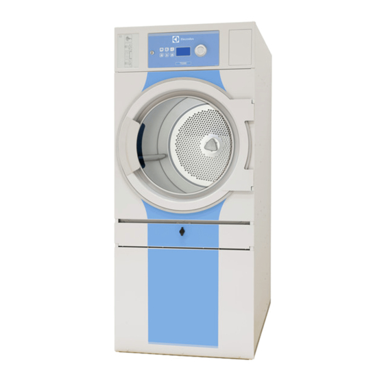
Page 1: Tumble Dryer
Installation manual Tumble dryer T5290 Type N2... 438 9054-00/EN 2011.09.12 Installation manual in original language... -
Page 3: Table Of Contents
Contents Contents 1 Safety Precautions ......................5 2 Technical data ........................7 2.1 Drawing ........................7 2.2 Technical data......................8 2.3 Connections........................ 8 3 Setup..........................9 3.1 Unpacking........................9 3.2 Siting........................... 10 3.3 Mechanical installation ....................10 4 Marine installation ......................11 5 Reversing the door...................... -
Page 5: Safety Precautions
Safety Precautions 1 Safety Precautions The machine is not intended for use by persons (including children) with reduced physical, sensory or mental capabilities, or lack of experience and knowledge, unless they have been given supervision or instruction concerning use of the appliance by a person responsible for their safety. Children should be supervised to ensure that they do not play with the machine. - Page 6 Safety Precautions In order to prevent damage to the electronics (and other parts) that may occur as the result of condensation, the machine should be placed in room temperature for 24 hours before being used for the first time.
-
Page 7: Technical Data
Technical data 2 Technical data 2.1 Drawing B(b) B(a) Operating panel Door opening, ⌀ 580 mm Electrical connection Gas connection Exhaust connection Steam: in Steam: out B(a) B(b) 1155 1335 1675 1310 1380... -
Page 8: Technical Data
Technical data 2.2 Technical data Weight, net Drum volume litres Drum diameter Drum depth Drum speed G-factor, max. 0.94 Capacity, filling factor 1:18 (Max. load) 16.1 Capacity, filling factor 1:22 (Recommended. load) 13.2 Heating: Electricity 13.5 Heating: Gas Heating: Steam Air consumption, Electric heating, 13.5 kW Air consumption, Electric heating, 18.0 kW Air consumption, Gas heating... -
Page 9: Setup
Setup 3 Setup 3.1 Unpacking Note! Two persons are recommended for the unpacking. The machine is delivered complete with supporting feet. The machine is delivered bolted onto the transport pallet and packed in a crate or box. Remove packing from the machine. Remove the bolts between the machine and pallet. -
Page 10: Siting
Setup 3.2 Siting The machine should be positioned so that there is plenty of room for working, both for the user and service personnel. The figure shows minimum distance to a wall and/or other machines. Max. 50 mm / 1 15/16 inch Min. -
Page 11: Marine Installation
Marine installation 4 Marine installation To ensure steadiness of the machine it is important to fasten the machine to the foundation. Fasten the four fittings (supplied with the marine machine model) to the foundation using four x M10 set screws. If the four fittings is not supplied, order kit Nr. 487193544. Fasten the machine to the fittings. -
Page 12: Reversing The Door
Reversing the door 5 Reversing the door Disconnect the power to the machine. Demount the hinges and remove the door. Remove the upper hinge first. fig.7166 ⑤ Remove the screws on the front panel and carefully loosen the panel. Disconnect the door switch cable and remove the panel. - Page 13 Reversing the door Move the door switch cable to the opposite site. Note! The plastic plug MUST be placed in the hole where the door switch cable was before. fig.7170 ⑦ Loosen the nuts and move the two brackets to the opposite side. fig.7171 ⑧...
- Page 14 Reversing the door Move the door switch on the front panel. fig.7172 ⑨ Move the four metal clips from the right side to the left side. fig.7174 ⑩ Connect the door switch cable and remount the front panel. Fasten the hinges and mount the door on the opposite side than before. Connect the power to the machine.
-
Page 15: Evacuation System
Evacuation system 6 Evacuation system 6.1 Air principle The fan creates low pressure in the machine, drawing air into the drum via the heating unit. The heated air passes through the garments and the drum holes. The air then flows outh through a lint filter positioned below the drum. Then the air is evacuated through the fan and exhaust system. -
Page 16: Fresh Air
Evacuation system 6.2 Fresh air For maximum efficiency and the shortest possible drying time, it is important to ensure that fresh air is able to enter the room from the outside in the same volume as that blown out of the room To avoid draught in the room it is important to place the air inlet behind the machine. -
Page 17: Exhaust Duct
Evacuation system 6.3 Exhaust duct • Only rigid or flexible metal duct should be used for exhausting. • Plastic ducting is not to be used. • Recommended material for exhaust is galvanised steel. • The duct is not to be assembled with screws of other fastening means that extend into the duct and catch lint. -
Page 18: Shared Exhaust Duct
Evacuation system 6.4 Shared exhaust duct It is recommended that each machine is connected to a separate exhaust duct. When several machines shall use the same exhaust duct the exhaust duct must increase after each machine. ⑮ Number of machines Exhaust duct ⌀... -
Page 19: Exhaust Dimensioning
Evacuation system 6.5 Exhaust dimensioning It is important that the machine has correct air volume compared to each machines power. If the air volume is smaller or bigger this will result in a longer drying period. The machine is designed to work with 25 m outlet pipe and two 90 degree bends. Each bend is equal to 2.5 m. -
Page 20: Steam Connection
Steam connection 7 Steam connection 7.1 Connecting the steam Note! The steam pipe must be cut off and must not be under pressure. • The branch pipe’s must be located at the top of the main steam pipe to prevent condensation in the steam. -
Page 21: Steam Calorifier
Steam connection 7.2 Steam calorifier Mount the steam calorifier Unpack the steam calorifier. Demount the back plate on the machine. Demount the supporting rail on the machine (A). Note which way the supporting rail turns as it has to be remounted the same way. ⑰... - Page 22 Steam connection When ready Leak test the system. Clean the dirt collectors. Perform a function chek.
-
Page 23: Gas Connection
Gas connection 8 Gas connection 8.1 Fasten the label Before installing the machine fasten the label “Read the user instructions” on the inside of the door in a suitable place and at the front panel. The label must have the correct country code, choose the correct label from the gas kit. Not applicable for Japan. -
Page 24: Gas Installation
Gas connection 8.3 Gas installation This gas appliance is build to run on natural gas (group I2H and I2E), commonly identified by GNH. Japan to run on LPG (group I3B/P). The data label shows the injector size and the injector pressure and the countries that use this gas quality: Albania Iceland... -
Page 25: Table Of Pressure And Adjustment
Gas connection 8.4 Table of pressure and adjustment Liquied Inlet Burner Injector size Air reducing Label May be petroleum pressure pressure (mm) plate (mm) number available category gases (mbar) (mbar) in following countries Butane I3B/P 30, 37 or 50 490375644 BE, CY, DK, EE, FR, GB, HU, IT, LT,... -
Page 26: Test Run
Gas connection 8.5 Test run Loose the pressure measuring tap screw (2) 1/4 of a turn. Connect a manometer to the measuring tap. Select a program that uses heat. Start the machine. Check the nozzle pressure, see table. If necessary adjust the regulator setting screw (4) behind the cover screw (3). Replace the cover screw (3) if removed. -
Page 27: Converting Instructions
Gas connection 8.6 Converting instructions Not applicable for Japan. Disconnect the power to the machine. Demount the lower back panel. Remove the nozzle (1). Mount the new supplied nozzle. fig.7127 Loosen the measuring branch screw (2) 1/4 turn; connect a manometer to the measuring branch. Connect the power to the machine and select a program with heat. - Page 28 Gas connection Check that the gas flame burns evenly. Mount the cover screw (3). Remount the lower back panel.
-
Page 29: Data Label
Gas connection 8.7 Data label When the machine is to be converted to another gas type, the data label at the rear of the machine must be updated in order for the data to be correct. Place the data label enclosed in the conversion kit on top of the data label as shown below. If there are more than one data label, select the label with the correct country code and gas type. -
Page 30: Electrical Connection
Electrical connection 9 Electrical connection 9.1 Electrical installation The electrical installation may only be carried out by qualified personnel. Machines with frequency-controlled motors can be incompatible with certain types of earth leakage circuit breaker. It is important to know that the machines are designed to provide a high level of personal safety, which is why items of external equipment such as earth leakage circuit breakers are not necessary. -
Page 31: Single-Phase Connection
Electrical connection 9.2 Single-phase connection Demount the cover plate from the supply unit. Connect the earth and other wires as shown. 1NAC L2/N When the installation is completed remount the cover plate and check: • that the drum is empty. •... -
Page 32: Three-Phase Connection
Electrical connection 9.3 Three-phase connection Demount the cover plate from the supply unit. Connect the earth and other wires as shown. 3NAC 3NAC When the installation is completed remount the cover plate and check: • that the drum is empty. •... -
Page 33: Electrical Connections
Electrical connection 9.4 Electrical connections Heating Main voltage Heating power Total power Recommended alternative fuse Electric heating 400–415V 3N ~ 50/60 13.5 14.5 400–415V 3N ~ 50/60 18.0 18.9 440–480V 3 ~ 13.5 14.5 440–480V 3 ~ 18.0 19.0 230–240V 3 ~ 50/60 18.0 19.0... -
Page 34: Functions For I/O-Cards
Electrical connection 9.5 Functions for I/O-cards The electrical schematic can be one of the following: 9.5.1 Central payment (22J) To start the machine from a central payment system, the payment system must transmit a start pulse to the machine. The start pulse can be either 230V or 24V. In order to receive a feedback signal once the machine has started, 230V or 24V must be connected to connection 19. -
Page 35: Central Payment (22J)
Electrical connection 9.5.2 Central payment (22J) The central payment or booking system shall transmit an active (high) signal to the machine once permission has been granted to start the machine. The signal must remain active (high) until the machine starts. The signal can be either 230V or 24V. In order to receive a feedback signal once the machine has started, 230V or 24V must be connected to connection 19. -
Page 36: External Coin Meter/Central Payment (22K)
Electrical connection 9.5.3 External coin meter/Central payment (22K) The signal received from external coin meters must be a pulse. fig.7438... -
Page 37: Price Reduction (22K)
Electrical connection 9.5.4 Price reduction (22K) By maintaining an activated (high) signal on connection 5 ("Price red"), the price of the program can be reduced. This function has a number of uses, including providing reductions during a specific period of the day. Whilst the signal remains active (high), the price of the program is reduced by the percentage entered in the price programming menu. -
Page 38: Option
Electrical connection 9.5 Option 9.5.1 External connection 100 mA A special connection terminal is located on the connection console. This connection can be used as external control of a fan. The terminal for external control is equipped with 220–240V max.100 mA and is intended solely for the operation of a contactor Max. -
Page 39: Function Check
Function check 10 Function check May only be carried out by qualified personnel. A function check must be made when the installation is finished and before the machine can be used. Check the automatic stop of the machine • Start the machine. •... - Page 40 Function check If the direction is wrong, swop two of the three phases to the left on the connection terminal. fig.7119 Check the heat • Let the machine work for five minutes on a program with heat. • Check that the heating is working by opening the door and feel if there is heat in the drum. Ready to use If all tests are OK the machine is now ready to be used.
- Page 41 A11 (2003) WN3..., N5... EN 61000-3-11 (2001) EXSM.X. EN 61000-6-2 (2005) WN3..., N4..., N5... EN 61000-6-3 (2007) N4... Försäkran om överensstämmelse EF-samsvarserklæring Electrolux Laundry Systems Sweden AB Electrolux Laundry Systems Sweden AB SE-341 80 Ljungby, Sverige SE-341 80 Ljungby, Sverige, försäkrar under eget ansvar att denna produkt, med typbeteckning och enl. ovan, är tillverkad i erklærer på eget ansvar at dette produktet, med typebetegnelse og produksjonsnummer som överensstämmelse med följande direktiv: angitt nedenfor, er produsert i samsvar med bestemmelsene i følgende direktiver:...
- Page 42 EXSM.X. W4600X EXSM.X. C240 H1... C260 H1... C240R H1... C260R H1... C290R H1... T4130 N1130.. T4190 N1190.. N1190.. T4250 N2... T4350 N2... T5290 N2... Ljungby 2011.06.21 T5550 N2... T5675 N2... Franco Panno Vice President Technical Operations 471 1531-43/21 Page 2/2...
- Page 43 Skrotning av maskin När maskinen inte längre skall användas måste den lämnas till en återvinningsstation för destruktion. Många detaljer i maskinen går att återanvända, men den innehåller även annat material som måste tas om hand på ett korrekt sätt. Lämna därför aldrig maskinen eller delar av maskinen i hushållsavfallet, eftersom det kan leda till hälsorisker eller skador på...
- Page 44 Electrolux Laundry Systems Sweden AB 341 80 Ljungby, Sweden www.electrolux.com/laundrysystems Share more of our thinking at www.electrolux.com...
Need help?
Do you have a question about the T5290 and is the answer not in the manual?
Questions and answers