Table of Contents
Advertisement
Advertisement
Table of Contents

Related Manuals for R.V.R. Electronica PJ1000-Light


Summary of Contents for R.V.R. Electronica PJ1000-Light
- Page 1 PJ1000-LIGHT User Manual Volume 1 Manufactured by Italy...
-
Page 2: Revision History
Editor 14/11/05 First Edition F. Ballarani 12/12/05 Power Supply Upgrade J. H. Berti PJ1000-LIGHT - User Manual Version 1.1 © Copyright 2005 R.V.R. Elettronica SpA Via del Fonditore 2/2c - 40138 - Bologna (Italia) Telephone: +39 051 6010506 Fax: +39 051 6011104 Email: info@rvr.it... -
Page 3: Table Of Contents
PJ1000-LIGHT Table of Contents Preliminary Instructions Warranty First Aid Treatment of electrical shocks Treatment of electrical Burns Unpacking General Description Quick guide for installation and use Preparation First power-on and setup Operation Management Firmware Front and Rear Panel Description Front Panel... - Page 4 PJ1000-LIGHT This page was intentionally left blank Rev. 1.1 - 12/12/05 User Manual...
-
Page 5: Preliminary Instructions
PJ1000-LIGHT To claim your rights under this warranty, you shold follow 1. Preliminary Instructions this procedure: Contact the dealer or distributor where you This manual is written as a general guide for those having previous knowledge and experience with this kind of equipment, well purchased the unit. -
Page 6: Treatment Of Electrical Burns
PJ1000-LIGHT • clear out mouth if necessary and observe for • Treat victim for shock as required. breathing • Arrange transportation to a hospital as quickly • if not breathing, begin artificial breathing as possible. (Figure 2): tilt head, pinch nostrils, make airtight seal, four quick full breaths. -
Page 7: Unpacking
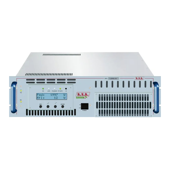
The PJ1000-LIGHT is an radio broadcasting amplifier manufactured by R.V.R. Elettronica SpA featuring adjustable RF power output up to 1000 W under 50 Ohm standard load and less than 20W drive power requirement. The PJ1000-LIGHT has been designed for installation in a 19”x3HE box for rack. The amplifier incorporates a low-pass filter to keep harmonics below the limits provided for by international standards (CCIR, FCC or ETSI). - Page 8 PJ1000-LIGHT The amplifier management software is based on a menu system. User has four navigation buttons available to browse submenus: ESC (chap. 6.1 - [6]), and ENTER (chap. 6.1 - [9]). The rear panel features the mains input connectors with a mains voltage switch (chap. 6.2 - [18]) to select the appropriate mains input voltage, RF input and output...
-
Page 9: Quick Guide For Installation And Use
PJ1000-LIGHT 5. Quick guide for installation and use This section provides a step-by-step description of the machine installation and configuration procedure. Follow these procedures closely upon first power-on and each time any change is made to general configuration, such as when a new transmission station is added or the exciter is replaced. Once the desired configuration has been set up, no more settings are required for normal operation; at each power-up (even after an accidental shutdown), the amplifier defaults to the parameters set during the initial configuration procedure. - Page 10 PJ1000-LIGHT 5.1.2 Mains power supply WARNING: Disconnect mains power supply before beginning these procedures. Both power supply units (please see chapter 8.1 for a detailed description) are equipped with fuses and voltage selection blocks: check all fuses and voltage selection blocks to ensure they are properly rated for the power mains and change them as required to match mains voltage.
- Page 11 PJ1000-LIGHT Figure 5.1: Voltage selection jumper on PFC 5.1.3 Connections Connect the output of a suitable FM exciter (for instance, PTX30-LCD exciter available from R.V.R. Elettronica) to the RF input (see figure 6.2 - item [8]) using a 50-Ohm coaxial cable with “N”-type connectors. To begin with, set exciter to minimum output power and switch if off.
-
Page 12: First Power-On And Setup
PJ1000-LIGHT Figure 5.2: Connection to exciter 5.2 First power-on and setup Follow this procedure upon first power-on and after making changes to the configuration of the transmitter in which the amplifier is integrated. Note : Standard factory settings are RF power output Off (Pwr OFF) and output power set to upper limit (unless otherwise specified by customer). - Page 13 PJ1000-LIGHT 5.2.3 Power check Ensure that the ON light turns on (see figure 6.1 - item [1]). Machine name should appear briefly on the display, quickly followed by forward and reflected power readings (figure 5.2 - menu 1). If RF output is disabled, these readings will be zero. 5.2.4 How to enable Local mode and RF output Check current mode setting and enable Local mode (if not already enabled) following menu path Fnc ⇒...
- Page 14 PJ1000-LIGHT Open the Power setup menu (figure 5.2 - menu 2) pressing the following keys in the order: ESC (opens Default Menu) ⇒ ENTER (hold down for 2 seconds) Use SET menu keys to set the desired amplifier output power; the SET bar at the side provides a graphic display of set power, whereas the forward power value shown on the display (Fwd: xxxx W) gives actual output power reading, and may be lower than set power if an Automatic Gain Control is in limited- power mode (please read section 5.3 concerning RF power modulation for more...
-
Page 15: Operation
PJ1000-LIGHT 5.3 Operation 1) Power on the amplifier (chap. 6.1 - [11]) and ensure that the ON light turns on (chap. 6.1 - [1]). Machine name should appear briefly on the display, quickly followed by forward and reflected power readings (Menu 1), provided that the amplifier is delivering output power. Menu 1 1b) To modify power level setting, hold down the ENTER button until opening the power setup menu. The edit screen will look like this: Menu 2 Next to SET indication, a bar provides a graphic display of preset output power. -
Page 16: Management Firmware
PJ1000-LIGHT 2) Ensure that machine is not in a locked-out state. Press the ESC key (chap. 6.1 - [6]) to call up the selection screen (Menu 3). Highlight Fnc and press ENTER to confirm (chap. 6.1 - [9]) and access the appropriate menu (menu 4). If LOC is set to REMOTE (machine remote control), move cursor to LOC and press ENTER (chap. - Page 17 PJ1000-LIGHT (Three empty arrows) - Parameter is being edited. (Empty arrow) - Current line marker; the parameter in this line cannot be edited. This symbol appears in menus that take up more than two lines to aid browsing. Menu 2...
- Page 18 PJ1000-LIGHT To gain access to a submenu, select menu name (name is highlighted by cursor) using button and press the ENTER button (chap. 6.1 - [9]). Press ESC again (chap. 6.1 - [6]) to return to the default menu (menu 1).
- Page 19 PJ1000-LIGHT 5.4.2 Power Menu (Pwr) This screen holds all readings related to machine output power: Menu 5 Forward power reading. Reflected power reading. Input power reading. Note that these are readings, rather than settings, and cannot be edited (note the empty arrow). To change power setting, go to the default menu (menu 1) as outlined earlier.
- Page 20 PJ1000-LIGHT 5.4.4 Alarm Menu (Alm) This menu shows any alarm conditions occurring during machine operation. Alarm thresholds are preset at the factory. Menu 7 Counter of alarm conditions triggered by forward power. Counter of alarm conditions triggered by reflected power. Counter of alarm conditions triggered by input power.
- Page 21 PJ1000-LIGHT 1. Over Forward Power Forward power threshold exceeded. Alarm 1 2. Over Reflected Power Reflected power threshold exceeded. Alarm 2 3. Over Input Power Input power threshold exceeded. Alarm 3 Monitoring cycle is as follows: • An alarm condition occurs; • Alarm is displayed and device is locked out for 15 sec.;...
- Page 22 PJ1000-LIGHT II. Over Reflected Power Reflected power alarm display. Stop 2 III. Over Input Power Input power alarm display. Stop 3 Once the machine goes into “FAULT/LOCK” mode, it will no longer attempt to re-start; choose the appropriate reset procedure according to current machine setting: •...
- Page 23 PJ1000-LIGHT Menu 8 C address setting. The I C network address becomes significant when the exciter is connected in an RVR transmission system that uses this protocol. Do not change it unless strictly required. 5.4.6 Version Menu (Vrs) This screen holds machine version/release information: Menu 9 Note that these are readings, rather than settings, and cannot be edited (note the empty arrow).
-
Page 24: Front And Rear Panel Description
PJ1000-LIGHT 6. Front and Rear Panel Description This section describes the components found on the front and rear panel of PJ1000-LIGHT. 6.1 Front Panel Figure 6.1 [1] ON Green LED - Turns on when amplifier is powered on. [2] FAULT/LOCK Red LED - Turns on when machine is in permanent fault lock-out mode. -
Page 25: Rear Panel
PJ1000-LIGHT 6.2 Rear Panel Figure 6.2 [1] R.F. TEST Output with level -60 dB lower than output power level, suitable for modulation monitoring. Not suitable for spectrum analysis. [2] GSM SLOT-IN Reserved for future implementations [3] GSM ANT Reserved for future implementations [4] AIR FLOW Air grille. -
Page 26: Connectors Description
PJ1000-LIGHT 6.3 Connectors description 6.3.1 Service (for factory setting purposes only) Type: Female DB9 TX_D RX_D Internally connected to 6 Internally connected to 4 Internally connected to 8 Internally connected to 7 6.3.2 Left (MONO) / Right Type: Female XLR... -
Page 27: Technical Specifications
PJ1000-LIGHT 7. Technical Specifications 7.1 Mechanical characteristics Panel Size 483 mm (19”) x 132.5 mm (3 HE) Depth 550 mm Weight approx. 31 Kg Working Temperature -10 °C ÷ 50 °C, without condensing 7.2 Electrical characteristics General RF output power 0-1000 W adjustable with continuity... -
Page 28: Spare Parts
PJ1000-LIGHT Remote Connections Interlock IN BNC type female: by grounding the central conductor the transmitter is forced to stand- by mode. ponendo a massa il conduttore centrale il trasmettitore viene forzato in modo stand-by Interlock OUT BNC type female: in case the transmitter... -
Page 29: Operating Principles
“Technical Schedule” Vol.2. 8.1 Power supply The PJ1000-LIGHT power supply section is made up of a surge protection module and two power supply units: 1. Surge Protection module (see description in chap. 8.1.1): protects the machine from possible voltage surge events and electric discharges in the power mains. - Page 30 PJ1000-LIGHT 8.1.1 Mains power supply pulse protection (SLSRGPRPJ1KM) This module is enclosed in a sealed metal case (see figure 9.1 - item [8]); it features two externally mounted mains fuses (figure 6.2 - [7] and [20]) and accommodates a bank of surge arresters that protect the machine from any surge events in the power mains. Mains voltage is brought from this module to the main Power switch on the front panel (figure 6.1 - [11]), which relays it to the service transformer TR1 (figure 9.2...
-
Page 31: Interface Board (Sl012In1001)
PJ1000-LIGHT • Regulated power set to 0 Watt using the edit mode (menu 2, see chapter 5.2); • An alarm or fault condition has occurred (see chapter 5.3.4). 8.2 Interface board (SL012IN1001) This board performs the following tasks: • It uses AC voltage from transformer TR1 to generate and distribute service power supply over the panel board;... -
Page 32: Power Amplifier
PJ1000-LIGHT 8.5 Power amplifier The RF power amplification section consists in three power modules coupled through a Wilkinson splitter and combiner using strip-line technology. Each RF module (code SL010RF2001) provides 350 W rated power using a single active element built using MOS technology. RF modules are fed by the switching power supply via the Bias board. -
Page 33: Bias Board (Slbias1K3U-2)
PJ1000-LIGHT 8.7 BIAS board (SLBIAS1K3U-2) The main purpose of this board is to control and correct the bias voltage of the RF amplification section MOSFETs. It also provides a measure of the total current absorbed by the RF modules and incorporates a dedicated circuit for power supply fault reporting. -
Page 34: Identification And Access To The Modules
PJ1000-LIGHT 9. Identification and Access to the Modules The PJ1000-LIGHT is made up of various modules linked to each other through connectors so as to make maintenance and any required module replacement easier. 9.1 Top View The figure below shows the equipment top view with the various components pointed out. -
Page 35: Bottom View
PJ1000-LIGHT 9.2 Bottom View The figure 9.2 shows the equipment bottom view with the various components pointed out. figure 9.2 [1] Filter Board (SLFILPSPJ1KC) [2] PS LED Board (SLLEDPSTEX1K) [3] Interface Board (SL012IN1001) [4] TR1 Transformer (TRFTEX1000T) [5] Telemetry Board (SLTLMTXLCD03) User Manual Rev. 1.1 - 12/12/05 31 / 32... - Page 36 PJ1000-LIGHT This page was intentionally left blank 32 / 32 Rev. 1.1 - 12/12/05 User Manual...
Need help?
Do you have a question about the PJ1000-Light and is the answer not in the manual?
Questions and answers