Table of Contents
Advertisement
Advertisement
Table of Contents

Related Manuals for R.V.R. Electronica TEX30LCD/S


Summary of Contents for R.V.R. Electronica TEX30LCD/S
- Page 1 TEX30LCD/S USER MANUAL VOLUME1 Manufactured by R.V.R ELETTRONICA Italy...
- Page 2 Revision History Date Version Reason Editor 02/09/2018 Second Version J. H. Berti TEX30LCD/S - User Manual Version 2.0 © Copyright 2018 R.V.R. Elettronica SpA Via del Fonditore 2/2c - 40138 - Bologna (Italia) Telephone: +39 051 6010506 Fax: +39 051 6011104 Email: info@rvr.it...
- Page 3 TEX30LCD/S ELETTRONICA Technical Specifications TEX30LCD/S Parameters U.M. Value Notes GENERALS Frequency range 87.5 ÷ 108 Rated output power Continuously variable by software from 0 to maximum Modulation type F3E Direct carrier frequency Operational Mode Mono, Stereo, Multiplex Ambient working temperature °C...
- Page 4 TEX30LCD/S ELETTRONICA AUDIO INPUTS Connector XLR F Type Balanced Left / Mono Impedance 10 k or 600 Selectable by rear panel dip switches Input Level /Adjust -13 to +13 continuosly variable Connector XLR F Type Balanced Right Impedance 10 k or 600...
-
Page 5: Table Of Contents
TEX30LCD/S ELETTRONICA Table of Contents Preliminary Instructions Warranty First Aid Treatment of electrical shocks Treatment of electrical Burns General Description Unpacking Features Frontal Panel Description Rear Panel Description Connectors Description Installation and use Installation Operation Management Firmware Optional Function Identification and Access to the Modules... - Page 6 TEX30LCD/S ELETTRONICA This page was intentionally left blank User Manual Rev. 2.0 - 02/09/18...
-
Page 7: Preliminary Instructions
TEX30LCD/S ELETTRONICA IMPORTANT The symbol of lightning inside a triangle placed on the product, evidences the operations for which is necessary gave it full attention to avoid risk of electric shocks. The symbol of exclamation mark inside a triangle placed on the product, informs the user about the presence of instructions inside the manual that accompanies the equipment, im- portant for the efficacy and the maintenance (repairs). -
Page 8: First Aid
TEX30LCD/S ELETTRONICA Units returned without a return authorisation may • Do not stop chest compressions while giving be rejected and sent back to the sender. artificial breathing. Be sure to include a detailed report mentioning all • Call for medical help as soon as possible. -
Page 9: General Description
87.5 and 108 MHz, in step of 10 KHz, with an RF output power adjustable up to a maximum of 30 W into a 50 Ohm standard load. The TEX30LCD/S are designed to being contained into a 19” rack box of 2HE. 4.1 Unpacking The package contains: 1 TEX30LCD/S... - Page 10 TEX30LCD/S ELETTRONICA The TEX30LCD/S can operate throughout the frequency bank with no need for calibration or set-up. An LCD on the front panel and a push-button board provide for user interfacing with the microprocessor control system, which offers the following features: •...
-
Page 11: Frontal Panel Description
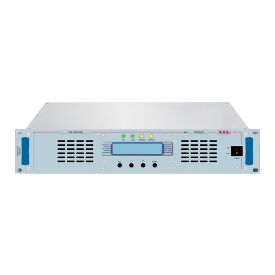
TEX30LCD/S ELETTRONICA 4.3 Frontal Panel Description [1] AIR FLOW Air flow for the forced ventilation. [2] ON Green LED, lit when the exciter is working. [3] LOCK Green led, lit when the PLL is locked on the working frequency. [4] FOLDBACK Yellow LED, lit when the foldback function is operating (automatic reduction of the delivered RF power). -
Page 12: Rear Panel Description
TEX30LCD/S ELETTRONICA 4.4 Rear Panel Description [1] PLUG VDE plug for mains supply. [2] FAN Fan for the forced ventilation of the exciter. [3] R.F. OUTPUT RF output connector, N-type, 50Ω. [4] PHASE ADJ Pilot tone phase adjustment trimmer. Pilot tone phase adjustment trimmer. . -
Page 13: Connectors Description
TEX30LCD/S ELETTRONICA [31] RFL EXT. AGC Trimmer for automatic gain control based on external signal of reflected power. [32] FWD EXT. AGC Trimmer for automatic gain control based on external signal of forward power. [33] RS232 Not used. [34] REMOTE DB15 connector for telemetry of the machine. -
Page 14: Installation And Use
TEX30LCD/S ELETTRONICA 5. Installation and use This section provides a step-by-step description of equipment installation and configuration procedure. Follow these procedures closely upon first power-on and each time any change is made to general configuration, such as when a new transmission station is added or the equipment is replaced. -
Page 15: Installation
TEX30LCD/S ELETTRONICA 5.1 Preparation 5.1.1 Preliminary Requirements The equiment ventilation and the work space must be suitable for maintenance operations according to the directive in force in the country in which this device is installed. It is necessary to leave a minimum distance of 50 cm on the front and back sides of the device to have a proper functioning and to facilitate air circulation through the ventilation grids. - Page 16 TEX30LCD/S ELETTRONICA TEX30LCD/S @ 90÷260 Vac Mains fuses (1x) 3.15A tipo 5x20 Table 5.1: Fuses 5.1.2 Placement of equipment Useful tips for a correct installation: • Do not use in presence of external elements near inlets and outlets ventilation systems, as they could prevent a proper ventilation of the device.
- Page 17 TEX30LCD/S ELETTRONICA The transmitter normally have the outlet air in the back of machine. In this case, provide adequate ventilation of the room. COLD In alternative is cooled by forced ventilation and the air outlet is located on the roof of machine.
- Page 18 Rack power supply connections Provide for the following (applicable to operating tests and putting into service): √ Mains power supply full range 80 ÷ 260 VAC full-range for TEX30LCD/S, both with adequate earth connection. √ For operating tests only: dummy load with 50 Ohm impedance and adequate capacity (30W as a minimum for TEX30LCD/S).
- Page 19 TEX30LCD/S ELETTRONICA N PE If transmitter require three-phase power with 3F (black, brown and grey) + N 3F (black, brown and grey) + N (blue) + GND (green yellow), keep in mind this requirement to connect to your , keep in mind this requirement to connect to your distribution board.
- Page 20 5.1.3 Device power supply connections Provide for the following (applicable to operating tests and putting into service): √ Mains power supply full range 80 ÷ 260 VAC full-range for TEX30LCD/S, both with adequate earth connection. √ For operating tests only: dummy load with 50 Ohm impedance and adequate capacity (30W as a minimum for TEX30LCD/S).
- Page 21 TEX30LCD/S ELETTRONICA Note: to ensure both the safety of the operators and the correct functioning of the apparatus, it is essential that the network system is grounded, and that it is properly connected to the equipment. Useful tips for a correct connection: •...
- Page 22 Ensure that the POWER switch on the front panel of TEX30LCD/S is set to “OFF”. The exciter has two switches: one is embedded in VDE socket for mains power cord and interrupts all mains power supply of the machine, while the second is on the front panel and acts by inhibiting the switching power supply of the machine.
- Page 23 TEX30LCD/S ELETTRONICA 5.1.5 First power-on and setup Perform this procedure upon first power-up and each time you make changes to the configuration of the transmitter this component is integrated into. Note : Standard factory settings are RF output power off (Pwr OFF) and regulated output power set to upper limit (unless otherwise specified by customer).
- Page 24 TEX30LCD/S ELETTRONICA actual output power reading, which may be lower than regulated power supply when Automatic Gain Control is running in power supply limitation mode (please read section 5.3 about RF power supply modulation for more details). Note: Output power may be set using the Pwr OFF control. In this condition, the output power readout (Fwd) on the display will read 0 (zero);...
-
Page 25: Operation
TEX30LCD/S ELETTRONICA To set subcarrier input levels, you may use the same procedure and option “x10” available in the Fnc menu. With this option, modulation level is multiplied by a factor of 10, which means that default menu bar meter reflects a 7.5 kHz deviation. - Page 26 TEX30LCD/S ELETTRONICA The screen that is shown is similar to the following: : Menu 2 NOTE: It is advisable to write down the password set, if you forget the password it is not possible to recover it automatically. To recover the password, contact Customer Service by sending the alphanumeric PUK code of 6 characters generated automatically when entering the password.
-
Page 27: Management Firmware
WARNING: Equipment is capable of delivering more than rated output power (30 W for TEX30LCD/S); however, never exceed the specified power rating. NOTE: If power is set to 0 W in the Power Setup Menu, the INTERLOCK OUT contact is activated and any external appliances connected to it are immediately inhibited. - Page 28 TEX30LCD/S ELETTRONICA Menu 2 Menu 1 Predefined menu Power Adjustment Menu Menu 3 Selection Menu Menu 4 Operation Menu Menu 5 Power Menu Menu 6 Power Amplifier Menu Menu 7 Settings Menu Menu 8 Miscellaneous Menu Menu 9 Versions Menu...
- Page 29 TEX30LCD/S ELETTRONICA As soon as operating conditions are restored, power output is re-enabled with the same settings in use prior to the alarm condition. Under 20kHz, no modulation occurs. After a preset time of about 5 minutes (not editable), a NO AUDIO condition is indicated in the main screen, but power is not inhibited.
- Page 30 [7] of the DB15 “Remote” connector located on the rear panel. Modifies Power Good threshold for reflected power. The Power Good rate is a percent of equipment rated power (3 W for TEX30LCD/S), not of reflected output power. This means that this threshold set at 5% will give 0,15 W regardless of set power level.
- Page 31 TEX30LCD/S ELETTRONICA 5.3.3 Power Amplifier (P.A) Menu This screen is made up of four lines that can be scrolled using the buttons and shows the readings relating to final power stage: Menu 7 Note that these are readings, rather than settings, and cannot be edited (note the empty arrow).
- Page 32 TEX30LCD/S ELETTRONICA 5.3.5 Miscellaneous Menu (Mix) This menu lets you set equipment address in an I C bus serial connection: Menu 9 IIC C address setting. The I2C network address becomes significant when the exciter is connected in an RVR transmission system that uses this protocol.
-
Page 33: Optional Function
TEX30LCD/S ELETTRONICA The bar meter reflects the level corresponding to a 100% deviation for each channel and provides a convenient reference when setting audio channel input levels. Menu 11 Left channel Vmeter. Right channel Vmeter.. 5.4 Optional Function A range of options is available for the product to add certain functions and/or modify existing functions. - Page 34 A brief description of the procedure is provided below: • Connect the PC serial port COM to the SERVICE connector on the rear panel of TEX30LCD/S using a standard Male DB9 - Female DB9 serial cable. • Power on the exciter;...
-
Page 35: Identification And Access To The Modules
ELETTRONICA 6. Identification and Access to the Modules 6.1 Identification of the Modules The TEX30LCD/S is made up of various modules linked to each other through connectors so as to make maintenance and any required module replacement easier. 6.1.1 TEX30LCD/S Upper view The figure below shows the equipment upper view with the various components pointed out. -
Page 36: Working Principles
TEX30LCD/S ELETTRONICA 7. Working Principles 7.1 Panel board The panel board contains the microcontroller (PIC18F452) that implements the equipment control software, the display and the other components needed to interface with the user. The board is connected with the other machine modules, both for power supply distribution and for the control and measures. -
Page 37: Telemetry Board
7.4 Power Supply The TEX30LCD/S power supply unit is a switching-type unit whose +28 V main output powers the machineÌs RF amplifier. The power supply also features stabilizers for generating continuous +5 V and +18 V voltages for supplying the other equipment circuits. -
Page 38: Control Board
TEX30LCD/S ELETTRONICA 7.6 Control Board The main function of this board is to check and correct the MOSFET polarization voltage of the RF amplifier section. It also provides the measurement of the absorbed current and contains a circuit for signaling power supply unit faults. -
Page 39: Maintenance And Repair Procedures
Be sure to disconnect the amplifier’s mains supply before proceeding to any maintenance operation on the system.. 8.3 Ordinary maintenance The only regular maintenance required on the TEX30LCD/S is the periodic blower replacement and dust cleaning of the air filter and of any trace of it inside the amplifier. -
Page 40: Module Substitutions
Only authorized and qualified technical personnel must be proceed with the replacement of the component parts in the relevant device. 8.4.1 How to replace the power supply • Open the top cover of TEX30LCD/S by unscrewing all the screws. • Identify the power supply module to be replaced. •... - Page 41 TEX30LCD/S ELETTRONICA • Disconnect all the connectors at positions B. • Unscrew all the points C with the help of a slotted screwdriver. • Remove the amplifier module and replace it with a new spare part. • Redo all previously steps, performed in reverse, in order to reassemble and fix the module in place.
- Page 42 • Open the top cover of TEX30LCD/S by unscrewing all the screws. • Identify the module to be replaced. • Unscrew the seven screws A on the rear panel of the TEX30LCD/S. User Manual / 42 Rev. 2.0 - 02/09/18...
- Page 43 TEX30LCD/S ELETTRONICA • Unscrew all screws B on the motherboard cover box. • Disconnect the connector C and unscrew the RF connector D. • Remove the main board and replace it with a new spare part. • Redo all previously steps, performed in reverse, in order to reassemble and fix the module in place.
- Page 44 TEX30LCD/S ELETTRONICA 8.4.4 How to replace the panel board • Unscrew the four screws A on the front panel of the TEX30LCD/S. • Disconnect all the connectors B. • Remove the panel board and replace it with a new spare part.
-
Page 45: Audigin-Tex Option
TEX30LCD/S ELETTRONICA 9. Option This section displays views on the variants compared to the basic version to be requested in the order. For more information about the options, rely on the respective user manuals. 9.1 \AUDIGIN-TEX option Digital Input Left (MONO) / Right... -
Page 46: Tlw-Tex-E-2He Option
TEX30LCD/S ELETTRONICA Service/RDS Type: DB9 Female 9.3 \TLW-TEX-E-2HE option Ethernet Type: RJ45 Female 1 TX+ 2 TX- 3 RX+ 4 NC 5 NC 6 RX- 7 NC 8 NC User Manual / 42 Rev. 2.0 - 02/09/18... -
Page 47: Tlw-Tex2He Option
TEX30LCD/S ELETTRONICA 9.4 \TLW-TEX2HE Option RS232 Bus Modem Type: DB9 Female Type: DB9 Female 1 NC 1 NC 2 TX_D 2 NC 3 RX_D 3 NC Internally connected with 5 GND 5 GND Internally connected with +12 V Internally connected with... -
Page 48: Power Up/Down Option (Only Software)
TEX30LCD/S ELETTRONICA 9.5 Power UP/DOWN Option (only software) The Power UP/DOWN option modifies the signal receive function for the signals present at the telemetry connector. RF section on / off control signals are treated as control signals for RF output power level to allow for UP/DOWN setting. - Page 49 ______________________________________________________________________________ ______________________________________________________________________________ ______________________________________________________________________________ ______________________________________________________________________________ ______________________________________________________________________________ ______________________________________________________________________________ ______________________________________________________________________________ ______________________________________________________________________________ ______________________________________________________________________________ ______________________________________________________________________________ ______________________________________________________________________________ ______________________________________________________________________________ ______________________________________________________________________________ ______________________________________________________________________________ ______________________________________________________________________________ ______________________________________________________________________________ ______________________________________________________________________________ ______________________________________________________________________________ ______________________________________________________________________________ ______________________________________________________________________________ ______________________________________________________________________________ ______________________________________________________________________________ ______________________________________________________________________________ ______________________________________________________________________________ ______________________________________________________________________________...
- Page 50 ______________________________________________________________________________ ______________________________________________________________________________ ______________________________________________________________________________ ______________________________________________________________________________ ______________________________________________________________________________ ______________________________________________________________________________ ______________________________________________________________________________ ______________________________________________________________________________ ______________________________________________________________________________ ______________________________________________________________________________ ______________________________________________________________________________ ______________________________________________________________________________ ______________________________________________________________________________ ______________________________________________________________________________ ______________________________________________________________________________ ______________________________________________________________________________ ______________________________________________________________________________ ______________________________________________________________________________ ______________________________________________________________________________ ______________________________________________________________________________ ______________________________________________________________________________ ______________________________________________________________________________ ______________________________________________________________________________ ______________________________________________________________________________ ______________________________________________________________________________...
- Page 51 ______________________________________________________________________________ ______________________________________________________________________________ ______________________________________________________________________________ ______________________________________________________________________________ ______________________________________________________________________________ ______________________________________________________________________________ ______________________________________________________________________________ ______________________________________________________________________________ ______________________________________________________________________________ ______________________________________________________________________________ ______________________________________________________________________________ ______________________________________________________________________________ ______________________________________________________________________________ ______________________________________________________________________________ ______________________________________________________________________________ ______________________________________________________________________________ ______________________________________________________________________________ ______________________________________________________________________________ ______________________________________________________________________________ ______________________________________________________________________________ ______________________________________________________________________________ ______________________________________________________________________________ ______________________________________________________________________________ ______________________________________________________________________________ ______________________________________________________________________________...
- Page 52 ISO 9001:2000 certified since 2000 R.V.R Elettronica S.p.A. Via del Fonditore, 2 / 2c Zona Industriale Roveri · 40138 Bologna · Italy Phone: +39 051 6010506 · Fax: +39 051 6011104 e-mail: info@rvr.it ·web: http://www.rvr.it The RVR Logo, and others referenced RVR products and services are trademarks of RVR Elettronica S.p.A. in Italy, other countries or both. RVR ® 1998 all rights reserved. All other trademarks, trade names or logos used are property of their respective owners.
Need help?
Do you have a question about the TEX30LCD/S and is the answer not in the manual?
Questions and answers