Table of Contents
Advertisement
Advertisement
Table of Contents

Related Manuals for R.V.R. Electronica TEX1000LIGHT


Summary of Contents for R.V.R. Electronica TEX1000LIGHT
- Page 1 TEX500-LCD & TEX1000LIGHT User Manual Volume 1 Manufactured by Italy...
-
Page 2: Revision History
Document History Date Version Reason Editor 27/10/2006 First Edition J. H. Berti TEX500-LCD&TEX1000light - User Manual Version 1.0 © Copyright 2006 R.V.R. Elettronica SpA Via del Fonditore 2/2c - 40138 - Bologna (Italia) Telephone: +39 051 6010506 Fax: +39 051 6011104 Email: info@rvr.it... -
Page 3: Table Of Contents
TEX500-LCD & TEX1000LIGHT Table of Contents Preliminary Instructions Warranty First Aid Treatment of electrical shocks Treatment of electrical Burns Unpacking General Description 5. Installation and configuration procedure Preparation First power-on and setup Operation Management Firmware Optional Functions Front and Rear Panel Description Front Panel... - Page 4 TEX500-LCD & TEX1000LIGHT This page was intentionally left blank Rev. 1.0 - 27/10/06 User Manual...
-
Page 5: Preliminary Instructions
TEX500-LCD & TEX1000LIGHT IMPORTANT The lightning flash with arrowhead, within a triangle, is intended to alert the user of the presence of dangerous voltage that may constitute a risk of electric shock. The exclamation point within an equilateral triangle is intended to alert the user to the presence of important operating and maintenance (servicing) instructions in the literature accompanying the equipment. -
Page 6: First Aid
TEX500-LCD & TEX1000LIGHT reason, we recommend insuring the goods for their full • One rescuer: give 2 quick rescue breaths after value. Returns must be sent on a C.I.F. basis (PREPAID) each 15 compressions. to the address stated on the authorisation as specified • Two rescuers: one rescue breath after each 5 by the R.V.R. -
Page 7: Unpacking
R.V.R. Elettronica SpA for audio radio broadcasting in the 87.5 to 108 MHz band in 10kHz steps, featuring adjustable RF output up to 500 and 1000 W, respectively, under 50 Ohm standard load. TEX500-LCD and TEX1000LIGHT have been designed for installation in a 3HE box for 19” rack. These transmitters incorporate a low-pass filter to keep harmonics below the limits provided for by international standards (CCIR, FCC or ETSI) and can be connected directly to the antenna. - Page 8 TEX500-LCD & TEX1000LIGHT • Measurement and display of transmitter operating parameters. • Communication with external devices such as programming or telemetry systems via RS232 serial interface or I2C. Four LEDs on the front panel provide the following status indications: ON, LOCK, FOLDBACK and RF MUTE;...
-
Page 9: Installation And Configuration Procedure
√ Single-phase 230 VAC or 115 VAC (-15% / +10%) mains power supply with adequate earth connection √ For operating tests only: dummy load with 50 Ohm impedance and adequate capacity (500W for TEX500-LCD or 1000W for TEX1000LIGHT as a minimum) √ Connection cable kit including: •... - Page 10 TEX500-LCD & TEX1000LIGHT 5.1.2 Mains power supply WARNING: Disconnect mains power supply before beginning these procedures. Both power supply units (please see section 8.1 for a detailed description) are equipped with fuses and voltage selection blocks; check all fuses and voltage selection blocks to ensure their are properly rated for the power mains and change them as required to match mains voltage.
- Page 11 TEX500-LCD & TEX1000LIGHT Figure 5.1: Voltage selection jumper on PFC 5.1.3 Connections Connect the RF output of the transmitter (see figure 6.2 - note [21]) to the antenna cable or a dummy load capable of dissipating amplifier output power. To begin with, set exciter to minimum output power and switch it off. Connect the transmitter INTERLOCK IN input (figure 6.2 - note [24]) to the matching INTERLOCK OUT output fitted on R.V.R. Elettronica equipment to act as hybrid couplers. If your equipment is a different brand, identify an equivalent output. WARNING: Electric shock hazard! Never handle the RF output connector when the equipment is powered on and no load is connected.
-
Page 12: First Power-On And Setup
TEX500-LCD & TEX1000LIGHT WARNING: The power supply connector is a terminal box. Ensure that the wire is not live before performing the connection. Connect the audio and RDS/SCA signals from user’s sources to the transmitter input connectors. 5.2 First power-on and setup Perform this procedure upon first power-up and each time you make changes to the configuration of the transmitter this component is integrated into. Note : Standard factory settings are RF output power off (Pwr OFF) and regulated output power set to upper limit (unless otherwise specified by customer). - Page 13 TEX500-LCD & TEX1000LIGHT Use the keys in the SET menu to set exciter output power; the setting bar at the side of SET provides a graphic indication of power setting; please consider that the forward power readout provided on the display (FWD: xxxx W) reflects...
- Page 14 TEX500-LCD & TEX1000LIGHT Input sensitivity in Stereo mode: Input Figure 6.2 Trimmer Sensitivity Note [12] [14] -20 ÷ +13 dBm Input level for 75 kHz deviation (0 dB) SCA1 [11] [15] - 8 ÷ +13 dBm Input level for 7,5 kHz deviation (-20 dB)
-
Page 15: Operation
TEX500-LCD & TEX1000LIGHT 5.3 Operation NOTE: For better clarity, only the typical screens of TEX1000LIGHT are reported below. TEX500-LCD screens look the same except that full scale values are different. 1) Power on the exciter (sect. 6.1 - [11]) and ensure that the ON light turns on (section 6.1 - note [1]). Equipment name should appear briefly on the display,... -
Page 16: Management Firmware
WARNING: Equipment is capable of delivering more than rated output power (500W for TEX500-LCD or 1000 W for TEX1000LIGHT); however, never exceed the specified power rating. NOTE: If power is set to 0 W in the Power Setup Menu, the INTERLOCK OUT contact (sect. - Page 17 TEX500-LCD & TEX1000LIGHT ...
- Page 18 TEX500-LCD & TEX1000LIGHT As soon as operating conditions are restored, power output is re-enabled with the same settings in use prior to the alarm condition. Under 20kHz, no modulation occurs. After a preset time of about 5 minutes (not editable), a NO AUDIO condition is indicated in the main screen, but power is not inhibited.
- Page 19 Modifies Power Good threshold for forward power. The Power Good rate is a percent of equipment rated power (500W for TEX500-LCD and 1000 W for TEX1000LIGHT), not of forward output power. This means that this threshold set at 50% will give 250 W and 500 W, respectively, regardless of set power level. The Power Good feature enables output power control and reporting.
- Page 20 TEX500-LCD & TEX1000LIGHT 5.4.3 Power Amplifier (P.A) Menu This screen is made up of four lines that can be scrolled using the buttons and shows the readings relating to final power stage: Menu 6 Note that these are readings, rather than settings, and cannot be edited (note the empty arrow). Voltage supplied by amplifier module. Current draw of amplifier module.
- Page 21 TEX500-LCD & TEX1000LIGHT IIC C address setting. The I C network address becomes significant when the exciter is connected in an RVR transmission system that uses this protocol. Do not change it unless strictly required. 5.4.6 Version Menu (Vrs) This screen holds equipment version/release information:...
-
Page 22: Optional Functions
TEX500-LCD & TEX1000LIGHT 5.5 Optional functions A range of options is available for the product to add certain functions and/or modify existing functions. Outlined below are the functions available at the moment, which must be specified on order. 5.5.1 FSK option The FSK function generates periodic carrier frequency shifts to generate a Morse- coded station ID code. - Page 23 A brief description of the procedure is provided below: • Connect the PC serial port COM to the SERVICE connector on the rear panel of TEX500-LCD and TEX1000LIGHT using a standard Male DB9 - Female DB9 serial cable. • Power on the exciter;...
-
Page 24: Front And Rear Panel Description
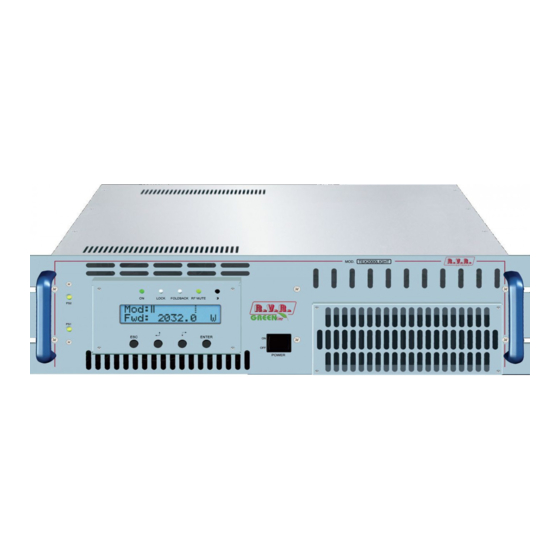
TEX500-LCD & TEX1000LIGHT 6. Front and Rear Panel Description This section describes the components found on the front and rear panel of TEX500-LCD and TEX1000LIGHT. 6.1 Front Panel Figure 6.1 [1] ON Green LED - Turns on when amplifier is powered on. [2] LOCK Green LED verde - Turns on when PLL is locked to operating frequency. -
Page 25: Rear Panel
TEX500-LCD & TEX1000LIGHT 6.2 Rear Panel Figure 6.2 [1] R.F. TEST Output with level -60 dB lower than output power level, suitable for modulation monitoring. Not suitable for spectrum analysis. [2] GSM SLOT-IN Reserved for future implementations. [3] GSM ANT Reserved for future implementations. -
Page 26: Connector Pinouts
TEX500-LCD & TEX1000LIGHT [30] SERVICE VOLTAGE SEL. 115-230V mains voltage selector. [31] I2C BUS DB9 connector for I2C bus network. [32] SERVICE FUSE Service fuse (sect. 5.1 - Table [1]). [33] LEFT ADJ Trimmer for left input level adjustment. [34] LEFT Left audio channel input XLR connector. - Page 27 TEX500-LCD & TEX1000LIGHT 6.3.4 Left (MONO) / Right Type: Female XLR Positive Negative 6.3.5 Remote Type: Female DB15 Pin Name Type Purpose Interlock Inhibits power if closed to Ext AGC FWD Ext. signal,1-12V, for limitation (AGC) Ground SDA IIC Serial data for IIC communication...
-
Page 28: Technical Specifications
TEX500-LCD & TEX1000LIGHT 7. Technical Specifications TEX 500PFC TEX 500REC TEX 1000 LIGHT Parameters Conditions U.M. Value Value Value Notes GENERALS Frequency range 87.5 ÷ 108 87.5 ÷ 108 87.5 ÷ 108 Rated output power 1000 Continuously variable by software from 0 to maximum... -
Page 29: Operating Principles
Following is a brief description of the different module functions; all diagrams and board layout diagrams are included in the “Technical Schedule” Vol.2. 8.1 Power supply TEX500-LCD and TEX1000LIGHT power supply sections are made up of a surge protection module and two power supply units: User Manual Rev. - Page 30 TEX500-LCD & TEX1000LIGHT 1. Surge Protection module (see description in sect. 8.1.1): protects the equipment from possible voltage surge events and electric discharges in the power mains. 2. Power amplifier supply unit: provides adequate power supply for RF power amplifier modules. It is a switching power supply unit with PFC full range; for details of the PFC and converter modules, please see sections 8.1.2 and 8.1.3, respectively.
-
Page 31: Interface Board (Sl010In3001)
TEX500-LCD & TEX1000LIGHT The PFC unit can operate on 115 VAC or 230 VAC input voltage. It features a voltage selection block that normally does not require setting: see section 5.1.2 for a detailed description. On TEX500-LCD, a conventional rectifier unit (without power factor correction) may also be installed in place of the PFC unit. -
Page 32: Panel Board - Cpu (Sl007Pc2001A)
TEX500-LCD & TEX1000LIGHT 8.3 Panel board - CPU (SL007PC2001A) The panel board accommodates the microcontroller that runs equipment firmware and all user interface elements (display, LEDs, keys, …). This board is interfaced with other equipment modules via flat cables and provides for power supply, control signals and measurement distribution. 8.4 Main Board (SLMBDTEXLC06) The main board performs the following tasks: •... -
Page 33: Power Amplifier
Each RF module of the TEX500-LCD (code SL010RF1001) provides 300 W rated power - which rise up to 350 W each for the TEX1000LIGHT RF modules (code SL010RF2001) - using a single active element built using MOS technology. RF modules are fed by the switching power supply via the Bias board. -
Page 34: External Telemetry Interface Board (Sltlmtxlcd03)
TEX500-LCD & TEX1000LIGHT • Temperature too high • Current draw of one RF module too high 8.9 External Telemetry Interface Board (SLTLMTXLCD03) This board provides an I/O interface for the CPU with the outside environment. All available equipment input and output signals are brought to the REMOTE DB15 connector (sect. -
Page 35: Identification And Access To The Modules
TEX500-LCD & TEX1000LIGHT 9. Module identification Both TEX500-LCD and TEX1000LIGHT are made up of several modules connected through connectors to facilitate maintenance and replacement (if needed). 9.1 Top view (TEX500-LCD) The figure below shows a top view of the equipment and component locations. Figure 9.1 [1] BIAS board (SLBIAS1K3U-2) [2] Low-pass filter board (SLLPFTEX1KL) [3] PS Filter board (SLFILPSPJ1KC) -
Page 36: Bottom View (Tex500-Lcd)
TEX500-LCD & TEX1000LIGHT 9.2 Bottom view (TEX500-LCD) Figure 9.2 below shows a bottom view of the equipment and component locations. Figure 9.2 [1] FAN2 (VTL9GL1224J) [2] Telemetry board (SLTLMTXLCD03) [3] Pulse Protection board (SLSRGPRPJ1KM) [4] TR1 transformer (TRFTEX1000T) [5] Interface board (SL010IN3001) -
Page 37: Top View (Tex1000Light)
TEX500-LCD & TEX1000LIGHT 9.3 Top view (TEX1000LIGHT) The figure below shows a top view of the equipment and component locations. Figure 9.3 [1] BIAS board (SLBIAS1K3U-2) [2] Low-pass filter board (SLLPFTEX1KL) [3] PS Filter board (SLFILPSPJ1KC) [4] Panel board (SL007PC2001A) [5] FAN1 (VTL4184) [6] Power Factor Correction board (PFCPSL1000) [7] 50V 34A power supply unit (PSL5034) -
Page 38: Bottom View (Tex1000Light)
TEX500-LCD & TEX1000LIGHT 9.4 Bottom view (TEX1000LIGHT) Figure 9.2 below shows a bottom view of the equipment and component locations. Figure 9.4 [1] FAN2 (VTL9GL1224J) [2] Telemetry board (SLTLMTXLCD03) [3] Pulse Protection board (SLSRGPRPJ1KM) [4] TR1 transformer (TRFTEX1000T) [5] Interface board (SL010IN3001)
Need help?
Do you have a question about the TEX1000LIGHT and is the answer not in the manual?
Questions and answers