Table of Contents
Advertisement
Quick Links
Advertisement
Table of Contents

Related Manuals for R.V.R. Electronica PJ700C-LCD


Summary of Contents for R.V.R. Electronica PJ700C-LCD
- Page 1 PJ500C-LCD, PJ700C-LCD & PJ1000-LIGHT User Manual Volume 1 Manufactured by Italy...
- Page 2 Date Version Reason Editor 24/06/08 First Edition J.H. Berti PJ500C-LCD, PJ700C-LCD & PJ1000-LIGHT - User Manual Version 1.0 © Copyright 2008 R.V.R. Elettronica SpA Via del Fonditore 2/2c - 40138 - Bologna (Italia) Telephone: +39 051 6010506 Fax: +39 051 6011104 Email: info@rvr.it...
-
Page 3: Table Of Contents
PJ500C-LCD, PJ700C-LCD & PJ1000light Table of Contents Preliminary Instructions Warranty First Aid Treatment of electrical shocks Treatment of electrical Burns Unpacking General Description Quick guide for installation and use Preparation First power-on and setup Operation Management Firmware Front and Rear Panel Description... - Page 4 PJ500C-LCD, PJ700C-LCD & PJ1000light This page was intentionally left blank Rev. 1.0 - 20/06/08 User Manual...
-
Page 5: Preliminary Instructions
PJ500C-LCD, PJ700C-LCD & PJ1000light To claim your rights under this warranty, you shold follow 1. Preliminary Instructions this procedure: Contact the dealer or distributor where you This manual is written as a general guide for those having previous knowledge and experience with this kind of equipment, well purchased the unit. -
Page 6: Treatment Of Electrical Burns
PJ500C-LCD, PJ700C-LCD & PJ1000light • clear out mouth if necessary and observe for • Treat victim for shock as required. breathing • Arrange transportation to a hospital as quickly • if not breathing, begin artificial breathing as possible. (Figure 2): tilt head, pinch nostrils, make airtight seal, four quick full breaths. -
Page 7: Unpacking
This design facilitates maintenance and module replacement. The RF power section of PJ500C-LCD uses two MOSFET modules delivering up to 300W output power each, PJ700C-LCD uses two MOSFET modules delivering up to 350W output power each, whereas PJ1000light features three MOSFET modules with up to 350 W output power each. - Page 8 PJ500C-LCD, PJ700C-LCD & PJ1000light Four LEDs on the front panel provide for machine status indication (ON, FAULT/ LOCK, FOLDBACK, RF MUTE) and two yellow LEDs provide Power Supply fault indication. The amplifier management software is based on a menu system. User has four navigation buttons available to browse submenus: ESC, , and ENTER.
-
Page 9: Quick Guide For Installation And Use
√ FM exciter with adjustable output power up to 20W (as a minimum), like RVR Elettronica PTX30-LCD √ For operating tests only: dummy load with 50 Ohm impedance and adequate capacity (500w for PJ500C-LCD, 700w for PJ700C-LCD or 1000 W for PJ1000light as a minimum) √ Connection cable kit including: •... - Page 10 PJ500C-LCD, PJ700C-LCD & PJ1000light 5.1.2 Mains power supply WARNING: Disconnect mains power supply before beginning these procedures. Both power supply units (please see chapter 8.1 for a detailed description) are equipped with fuses and voltage selection blocks: check all fuses and voltage selection blocks to ensure they are properly rated for the power mains and change them as required to match mains voltage.
- Page 11 PJ500C-LCD, PJ700C-LCD & PJ1000light Figure 5.1: Voltage selection jumper on PFC 5.1.3 Connections Connect the output of a suitable FM exciter (for instance, PTX30-LCD exciter available from R.V.R. Elettronica) to the RF input (see figure 6.2) using a 50-Ohm coaxial cable with suitable connectors. To begin with, set exciter to minimum output power and switch if off.
-
Page 12: First Power-On And Setup
PJ500C-LCD, PJ700C-LCD & PJ1000light Figure 5.2: Connection to exciter 5.2 First power-on and setup Follow this procedure upon first power-on and after making changes to the configuration of the transmitter in which the amplifier is integrated. Note : Standard factory settings are RF power output Off (Pwr OFF) and output power set to upper limit (unless otherwise specified by customer). - Page 13 Rfl and input power Inp readings. With drive power set as specified in the Final Test Table, amplifier output power should be 500W (for model PJ500C-LCD), 700W (for model PJ700C-LCD) or 1000W (for model PJ1000-light) or higher: if needed, fine tune drive power until achieving rated output power.
- Page 14 PJ500C-LCD, PJ700C-LCD & PJ1000light Open the Power setup menu (figure 5.2 - menu 2) pressing the following keys in the order: ESC (opens Default Menu) ⇒ ENTER (hold down for 2 seconds) Use SET menu keys to set the desired amplifier output power; the SET...
-
Page 15: Operation
5.3 Operation NOTE: For better clarity, only the typical screens of PJ1000light are reported below. PJ500C-LCD and PJ700C-LCD screens look the same except that full scale values are different. 1) Power on the amplifier (chap. 6.1) and ensure that the ON light turns on (chap. - Page 16 WARNING:Equipment is capable of delivering more than rated output power (500W for PJ500C-LCD, 700W for PJ700C-LCD or 1000 W for PJ1000-LIGHT); however, never exceed the specified power rating. NOTE: Exciter drive power setting should never exceed 20W, or it will trigger an Overdrive Alarm.
-
Page 17: Management Firmware
PJ500C-LCD, PJ700C-LCD & PJ1000light 5.4 Management Firmware The machine features an LCD with two lines by 16 characters that displays a set of menus. Figure 5.2 below provides an overview of machine menus. The symbols listed below appear in the left portion of the display as appropriate: (Cursor) - Highlights selected (i.e. - Page 18 PJ500C-LCD, PJ700C-LCD & PJ1000light When the display is off, touching any key will turn on backlighting. When the display is on, pressing the ESC button (chap. 6.1) from the default menu (menu 1) calls up the selection screen (menu 3), which gives access to...
- Page 19 Modifies Power Good threshold for forward power. The Power Good rate is a percent of equipment rated power (500W for PJ500C-LCD, 700W for PJ700C-LCD and 1000 W for PJ1000-LIGHT), not of forward output power. This means that this threshold set at 50% will give 250, 350 and 500 W, respectively, regardless of set power level.
- Page 20 PJ500C-LCD, PJ700C-LCD & PJ1000light Note that these are readings, rather than settings, and cannot be edited (note the empty arrow). Voltage supplied to amplifier module. Current absorbed to amplifier module. Efficiency based on ratio of forward power to amplifier module power in percent ( FWD PWR/(Vpa x Ipa) % ).
- Page 21 PJ500C-LCD, PJ700C-LCD & PJ1000light After the alarm condition has been rectified, the counter can be reset by highlighting “Reset Alm” and holding down the ENTER key for some time (chap. 6.1). 5.4.4.1 Alarms and Faults There are three types of alarms that can cause a machine lock-out and trigger a “FAULT/LOCK”...
- Page 22 PJ500C-LCD, PJ700C-LCD & PJ1000light Upon reaching the 10 cycle limit, a “FAULT/LOCK” indication is triggered and the device goes into lock-out mode; the appropriate LED turns on (figure 6.1]) and this screen is displayed: I. Over Forward Power Forward power alarm display.
- Page 23 PJ500C-LCD, PJ700C-LCD & PJ1000light Alarm 4 5.4.5 Miscellaneous Menu (Mix) This menu lets you set machine address in an I C bus serial connection: Menu 8 C address setting. The I C network address becomes significant when the exciter is connected in an RVR transmission system that uses this protocol.
-
Page 24: Front And Rear Panel Description
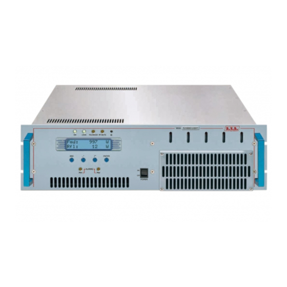
PJ500C-LCD, PJ700C-LCD & PJ1000light 6. Front and Rear Panel Description This section describes the components found on the front and rear panel of PJ500C-LCD, PJ700C-LCD and PJ1000-LIGHT. 6.1 Front Panel Figure 6.1 [1] ON Green LED - Turns on when amplifier is powered on. -
Page 25: Rear Panel
PJ500C-LCD, PJ700C-LCD & PJ1000light 6.2 Rear Panel Figure 6.2 [1] R.F. TEST Output with level -60 dB lower than output power level, suitable for modulation monitoring. Not suitable for spectrum analysis. [2] GSM SLOT-IN Reserved for future implementations [3] GSM ANT... -
Page 26: Connectors Description
PJ500C-LCD, PJ700C-LCD & PJ1000light 6.3 Connectors description 6.3.1 Service (for factory setting purposes only) Type: Female DB9 TX_D RX_D Internally connected to 6 Internally connected to 4 Internally connected to 8 Internally connected to 7 6.3.2 Remote Type: Female DB15... -
Page 27: Technical Specifications
PJ500C-LCD, PJ700C-LCD & PJ1000light 7. Technical Specifications 7.1 Generals Specifications PJ500C-LCD PJ700C-LCD PJ1000LIGHT Parameters Conditions U.M. GENERALS Frequency range 87.5 ÷ 108 87.5 ÷ 108 87.5 ÷ 108 Rated output power 1000 Input power for rated output Power supply type Mono phase... -
Page 28: Operating Principles
Following is a brief description of the different module functions; all diagrams and board layout diagrams are included in the “Technical Schedule” Vol.2. 8.1 Power supply PJ500C-LCD, PJ700C-LCD and PJ1000light power supply section is made up of a surge protection module and two power supply units: 24 / 32 Rev. - Page 29 PJ500C-LCD, PJ700C-LCD & PJ1000light 1. Surge Protection module (see description in chap. 8.1.1): protects the machine from possible voltage surge events and electric discharges in the power mains. 2. Power amplifier supply unit: provides adequate power supply for RF power amplifier modules. It is a switching power supply unit with PFC full range; for details of the PFC and converter modules, please see chapters 8.1.2 and 8.1.3,...
-
Page 30: Interface Board (Sl010In5001)
8.1.3 Switching power supply (PSL2403-03 and PSL5034) The switching power supply incorporated in this amplifier feeds 50 VDC to the RF power modules with 25 A maximum current for PJ500C-LCD and PJ700C-LCD and 34 A maximum for PJ1000light. This module has a control input that enables output voltage reduction when needed (for instance, in the event of RF output power reduction). -
Page 31: Pwr Input Measure Board (Slmpippj1Kc)
Wilkinson splitter and combiner using strip-line technology. Each RF module of the PJ500C-LCD (code SL010RF1002) provides 300 W rated power - which rise up to 350 W each for the PJ700C-LCD and PJ1000light RF modules (code SL010RF2002) - using a single active element built using MOS technology. -
Page 32: Bias Board (Slbias1K3U-2)
PJ500C-LCD, PJ700C-LCD & PJ1000light A directional coupler is provided at filter output to measure forward and reflected RF output power; power readings are relayed to the Interface and Bias boards to enable processing and display. The LPF board incorporates an RF output (having a level about -60 dB lower than output level) which is brought to a BNC connector (figure 6.2). -
Page 33: Identification And Access To The Modules
PJ500C-LCD, PJ700C-LCD & PJ1000light 9. Identification and Access to the Modules Both PJ500C-LCD, PJ700C-LCD and PJ1000-LIGHT are made up of various modules linked to each other through connectors so as to make maintenance and any required module replacement easier. 9.1 Top View (PJ500C-LCD and PJ700C-LCD) The figure below shows the equipment top view with the various components pointed out. -
Page 34: Bottom View (Pj500C-Lcd)
PJ500C-LCD, PJ700C-LCD & PJ1000light 9.2 Bottom View (PJ500C-LCD and PJ700C-LCD) The figure below shows the equipment bottom view with the various components pointed out. Figure 9.2 [1] Filter PS Board (SLFILPSPJ1KC) [2] LED PS Board (SLLEDPSTEX1K) [3] Interface Board (SL010IN5001) -
Page 35: Top View (Pj500C-Lcd)
PJ500C-LCD, PJ700C-LCD & PJ1000light 9.3 Top View (PJ1000light) The figure below shows the equipment top view with the various components pointed out. Figure 9.3 [1] Bias Board (SLBIAS1K3U-2) [2] Pass-through Filter Board (SLFILPJ1KM) [3] Low Pass Filter Board (SLLPFTEX1KL) [4] Panel Board (SL007PC2003) -
Page 36: Bottom View (Pj500C-Lcd)
PJ500C-LCD, PJ700C-LCD & PJ1000light 9.4 Bottom View (PJ1000light) The figure below shows the equipment bottom view with the various components pointed out. Figure 9.4 [1] Filter PS Board (SLFILPSPJ1KC) [2] LED PS Board (SLLEDPSTEX1K) [3] Interface Board (SL010IN5001) [4] TR1 Transformer (TRFTEX1000T)
Need help?
Do you have a question about the PJ700C-LCD and is the answer not in the manual?
Questions and answers