Table of Contents
Advertisement
Advertisement
Table of Contents

Related Manuals for R.V.R. Electronica PTRL


Summary of Contents for R.V.R. Electronica PTRL
- Page 1 PTRL & RXRL LCD User Manual Volume 1 Manufactured by Italy...
- Page 2 02/06/04 PTRL LCD Rear Panel Upgrade J. Berti 31/01/05 Added Chapter 11 J. Berti PTRL & RXRL LCD - User Manual Version 1.2 © Copyright 2003-2005 R.V.R. Elettronica SpA Via del Fonditore 2/2c - 40138 - Bologna (Italia) Telephone: +39 051 6010506...
-
Page 3: Table Of Contents
2. Warranty 3. First Aid 3.1 Treatment of electrical shocks 3.2 Treatment of electrical Burns 4. General description 5. PTRL-LCD quick guide for installation and use 5.1 Preparation 5.2 Use 5.3 Settings and calibration 5.4 Software 6. RXRL-LCD quick guide for installation and use 6.1 Preparation... - Page 4 PTRL & RXRL LCD 10. Functioning principles of the RXRL-LCD 10.1 Power supply 10.2 Power supply interface 10.3 Panel card 10.4 IF Card 10.5 Front End 10.6 VCO/PLL 10.7 Telemetry card 11. Procedure for change frequency of the radio link 11.1 Introduction...
-
Page 5: Preliminary Instructions
PTRL & RXRL LCD 1. Preliminary Instructions This manual is written as a general guide for those having previous knowledge and experience with this kind of equipment, well conscious of the risks connected with the operation of electrical equipment. It is not intended to contain a complete statement of all safety rules which should be observed by personnel in using this or other electronic equipment. - Page 6 PTRL & RXRL LCD This page was intentionally left blank 2 / 44 Rev. 1.2 - 31/01/05 User Manual...
-
Page 7: Warranty
PTRL & RXRL LCD 2. Warranty Any product of R.V.R. Elettronica is covered by a 24 (twenty-four) month warranty. For components like tubes for power amplifiers, the original manufacturer’s warranty applies. R.V.R. Elettronica SpA extends to the original end-user purchaser all manufacturers warranties which are transferrable and all claims are to be made directly to R.V.R. - Page 8 PTRL & RXRL LCD 4 Be sure to enclose a written technical report where mention all the problems found and a copy of your original invoice establishing the starting date of the warranty. Replacement and warranty parts may be ordered from the following address. Be sure to include the equipment model and serial number as well as part description and part number.
-
Page 9: First Aid
PTRL & RXRL LCD 3. First Aid The personnel employed in the installation, use and maintenance of the device, shall be familiar with theory and practice of first aid.. 3.1 Treatment of electrical shocks 3.1.1 If the victim is not responsive Follow the A-B-C's of basic life support •... -
Page 10: Treatment Of Electrical Burns
PTRL & RXRL LCD 3.1.2 If victim is responsive Keep them warm • Keep them as quiet as possible • Loosen their clothing (a reclining position is recommended) • • Call for medical help as soon as possible 3.2 Treatment of electrical Burns 3.2.1 Extensive burned and broken skin... -
Page 11: General Description
This type of equipment is often called STL (Studio-to-Transmitter Link). The PTRL-LCD is designed to work in an optimum way when connected to the receiver RXRL-LCD. Externally, it is a box to mount in a 19" rack, each one being 2HE high. - Page 12 PTRL & RXRL LCD Both the PTRL-LCD and the RXRL-LCD were designed in a modular way: the different functions are executed by modules connected directly with male and female connectors or with flat cables with connectors at both ends. This type of design makes the maintenance and the possible replacement of modules an easy operation.
-
Page 13: Ptrl-Lcd Quick Guide For Installation And Use
Check that the switches of the PTRL-LCD are in the position "0" (off). The PTRL-LCD has 2 switches: one is included in the VDE socket for the AC supply cable and interrupts completely the AC supply of the unit, while the second is situated on the front pannel and his action is to inhibit the switching power supply of the unit. -
Page 14: Use
From the menu "Fnc", set the power output. 5.3 Settings and calibration The only regulations that should be done manually on the PTRL-LCD are the regulations of the levels and audio functioning modes. On the rear pannel of the unit there is a trimmer for each input of the exciter; the silk- screnn of the pannel indicated to which input each trimmer refers to. -
Page 15: Software
PTRL & RXRL LCD For the regulation of the levels of the sub-carriers' inputs, a similar procedure can be followed, with the help of the option "X10" which can be selected from the menu Fnc. With this option, the indicated modulation level is multiplied per the factor 10, so that the hachured indication of the predefined menu coincides with a deviation value of 7,5 kHz. - Page 16 PTRL & RXRL LCD The vertical bars near the title "Mod" indicate the progress of the modulation in real time; the hachured bar indicates the maximum 75 kHz nominal modulation level (100%). In order to change the power level setted, select with the push-button GIU' the line which corresponds to the power and keep the ENTER button pressed until you enter the modify mode.
- Page 17 The threshold that can be setted (Power Good) refers to the transmitted power level. The threshold is expressed in percentage of the full scale of the considered size. The full-scale of the monitored size of the attention threshold for the PTRL-LCD is: •...
- Page 18 PTRL & RXRL LCD The values indicated are "readings", and therefore cannot be modified (remark the empty triangle). In order to modify the power setting, use the predefined menu as described formerly. 5.4.3 Power Amplifier menu (P.A) This view, composed of three lines that can be scrolled with the 'UP' and 'DOWN'...
- Page 19 PTRL & RXRL LCD 5.4.6 Versions Menu (Vrs) zThis view shows the version of the unit and the date to the software release. 5.4.7 Channels menu (L&R) This menu works on stereo version units. The input levels of the right and left channels are represented by vertical bars as indicated in the following illustration.
- Page 20 PTRL & RXRL LCD Pagina lasciata intenzionalmente in bianco 16 / 44 Rev. 1.2 - 31/01/05 User Manual...
-
Page 21: Rxrl-Lcd Quick Guide For Installation And Use
PTRL & RXRL LCD 6. RXRL-LCD quick guide for installation and use This chapter contains the necessary instructions for the installation and use of the equipment. In case some aspects are not totally clear, for instance when a user is using this equipment for the first time, we advise the new user to read carefully the entire description contained in this manual. -
Page 22: Use
PTRL & RXRL LCD 6.2 Use Switch on the receiver by putting the selector on the position "I" (on) the switch situated on the rear pannel. Enter the menu "Set" and set the working frequency desired. For the description of the different menus, read the chapter 6.4. -
Page 23: Software
PTRL & RXRL LCD As for the stereo version, there is an appropriate menu in which the levels of the of the right and left channels with the corresponding nominal level indicators for the maximum 75Khz deviation are indicated separately. - Page 24 PTRL & RXRL LCD When you press twice on the ESC button while you are in the predefined menu, the following selection view is displayed, and from this view it will be then possible to enter to all the other menus: To enter one of the submenus, select the name (that will be enhanced by a flashing cursor) with the RIGHT or LEFT push-buttons and then press the ENTER button.
- Page 25 PTRL & RXRL LCD 6.4.2 Set menu (Set) This menu enables to read and set the working frequencies . When you press the ENTER button, it will be possible to modify the setted frequency with the 'UP' (the frequency increases) and 'DOWN' (the frequency decreases).
- Page 26 PTRL & RXRL LCD 6.4.5 Versions menu (Vrs) This view shows the version of the unit and the date to the software release. 22 / 44 Rev. 1.2 - 31/01/05 User Manual...
-
Page 27: External Description
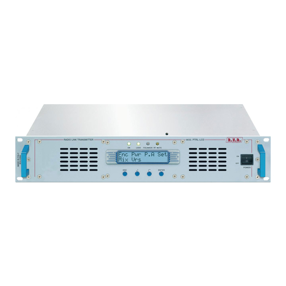
7. External Description This chapter describes the elements which are present on the front and rear pannel of the PTRL-LCD and the RXRL-LCD. 7.1 Front Panel of the PTRL LCD Figure 7.1 [1] AIR FLOW Grid for the air flow... -
Page 28: Rear Pannel Of The Ptrl-Lcd
PTRL & RXRL LCD 7.2 Rear pannel of the PTRL-LCD Figure 7.2 [1] P.A BLOCK Fuse-holder. Contains the protection fuse for the 3,15 A.power supply [2] R.F. OUTPUT RF Output connector N type, 50Ω. [3] INTERLOCK BNC interlock connector: When the main conductor is grounded, the transmitter is forced to go in stand-by mode. -
Page 29: Description Of The Connectors
PTRL & RXRL LCD 7.3 Description of the connectors 7.3.1 RS 232 Type: DB9 female TX_D RX_D Internally connected to 6 Internally connected to 4 Internally connected to 8 Internally connected to 7 7.3.2 Remote Type: DB15 female Interlock FWD fold... -
Page 30: Front Pannel Of The Rxrl-Lcd
PTRL & RXRL LCD 7.4 Front pannel of the RXRL-LCD Figure 7.4 [1] AIR FLOW Grid for the air flow [2] ON Green LED, illuminato when the transmitter is feeded [3] LOCK If it is on, indicates that the VCO is locked at the reference... -
Page 31: Rear Pannel Of The Rxrl-Lcd
PTRL & RXRL LCD 7.5 Rear pannel of the RXRL-LCD Figure 7.4 [1] MAINS VOLTAGE Plug for the AC voltage, 85-264V 50-60Hz. [2] R.F. INPUT 50 Ω RF input connector N type, 50Ω. [3] MUTE BNC interlock connector for the muting of the audio outputs with an external command. -
Page 32: Description Of The Connectors
PTRL & RXRL LCD 7.6 Description of the connectors 7.6.1 RS 232 Type: DB9 female TX_D RX_D Internally connected to 6 Internally connected to 4 Internally connected to 8 Internally connected to 7 7.6.2 Remote Type: DB15 female Interlock FWD fold... -
Page 33: Specifiche Tecniche
483 mm (19”) x 88 mm (3 1/2”) (2 HE) Depth 344 mm (26 1/2”) Weight About 6 Kg -10 °C ÷ 50 °C Working temperature 8.2 Electrical characteristics of the PTRL LCD General RFoutput power 0-10 W continuously selectable RF output connector Type "N" RF output impedance 50 Ohm 220 ÷... - Page 34 PTRL & RXRL LCD SCA1 and SCA2 inputs 2 connectors BNC type unbalanced IImpedance of the SCA1 and SCA2 inputs 10 kOhm -20 dBm ÷ +13 dBm for a 2,0 kHz deviation Level of the SCA1 and SCA2 inputs adjustable by trimmer...
-
Page 35: Electrical Characteristics Of The Rxrl-Lcd
PTRL & RXRL LCD 8.3 Electrical characteristics of the RXRL-LCD General RF output connector Type "N" RF output impedance 50 Ohm 220 ÷ 240 MHz Frequency band 420 ÷ 440 MHz 900 ÷ 960 MHz (Other frequency bands are available unpon... -
Page 36: Electrical Characteristics Of The Ptrl + Rxrl-Lcd
Female DB9 RS232 Telemetry connector DB15 type female, supplies indications on the status of the unit 8.4 Electrical characteristics of the PTRL + RXRL-LCD Mono Functioning S/N FM > 65dB against a 75KHz measured in the 40 Hz ¸ 15KHz band with deenphasis 50 us, detector RMS ≤... -
Page 37: Functioning Principles Of The Ptrl-Lcd
PTRL & RXRL LCD 9. Functioning principles of the PTRL-LCD The PTRL-LCD is composed of several modules connected between them with the help of connectors, with the aim to ease the maintenance and the possible replacement of the modules. The above description shows the top view of the unit with the indication of the different components. -
Page 38: Power Supply
9.1 Power supply The power supply of the PTRL-LCD is a switching unit whose 24V main output will formerly be reduced in order to supply the RF stage of the unit. The stabilizers for the 5V and 18V continuous voltage generation for the supply of the other circuits of the unit are present on the power supply. -
Page 39: Pannel Card
PTRL & RXRL LCD 9.3 Pannel card The pannel card contains the microprocessor (PIC16F877Q) which implements the monitoring software of the unit, the display and the other elements which are necessary for the interface with the user. This card is the interface with the other modules of the unit, both for the distribution of the supply units and monitoring and for the measurements. -
Page 40: Power Amplifier
PTRL & RXRL LCD 9.5.3 PLL/VCO stage This stage of the card generates the modulated radiofrequency signal. It is based on a PLL scheme which uses an integrated PLL model MB15E06. 9.5.4 Driver stage Before going through the final stage (power amplifier), the RF signal is preamplified in this stage by the BFR540 transistor. -
Page 41: Functioning Principles Of The Rxrl-Lcd
PTRL & RXRL LCD 10. Functioning principles of the RXRL-LCD The RXRL-LCD is composed of several modules connected between them with the help of connectors, with the aim to ease the maintenance and the possible replacement of modules. The above description shows the top view of the unit with the indication of the different components. -
Page 42: Power Supply
PTRL & RXRL LCD A schematic view of the modules and of the connections which compose the RXRL- LCD is shown in the following illustration. PANEL CARD BATTERY INTERFACE IF/AUDIO OUT VCO/PLL FRONTEND POWER SUPPLY RF CONNECTION DC CONNECTION A brief description of the functions of each module will follow, while the complete schemes and the layouts of the cards are shown in the appendix. -
Page 43: Panel Card
PTRL & RXRL LCD power supply interface, which is used automatically in order to collide with possible AC supply absences. 10.3 Panel card The panel card contains the microprocessor (PIC16F877Q) which implements the monitoring software of the unit, the display and the other elements which are necessary for the interface with the user. -
Page 44: Vco/Pll
PTRL & RXRL LCD The signal obtained comes sended to IF card for successive elaborations. 10.6 VCO/PLL This card receives the signal which is equivalent to the setted frequency which comes from the CPU of the panel card. In order to realize the operations, it is necessary to have a splitter which processes the information received and sends them back to the PLL stage. -
Page 45: Procedure For Change Frequency Of The Radio Link
11.1 Introduction This chapter introduces the procedures of alignment between the transmitter PTRL- LCD and the receiver RXRL-LCD. For the PTRL-LCD it is only necessary to program the new frequency through the Set menù (See Cap. 5.4.4). 11.2 Frequency Alignment... - Page 46 PTRL & RXRL LCD NOTE: The partial opening of the cover is necessary in order to avoid that the operator can come in contact with potentially harmful parts for the presence of high-voltage current. 2 - In case the holes are present on the cover: On the more recent models the holes are present directly on the cover.
- Page 47 PTRL & RXRL LCD ) Switch on the receiver and wait until that the lock has not happened on the working frequency (LOCK led lit on). In order to control or to modify that the working frequency is same to that one of the transmitter go to the Set menù (see cap.6.4.2)
- Page 48 PTRL & RXRL LCD This page was intentionally left blank 44 / 44 Rev. 1.2 - 31/01/05 User Manual...
Need help?
Do you have a question about the PTRL and is the answer not in the manual?
Questions and answers