
Related Manuals for R.V.R. Electronica BLUES30NV


Summary of Contents for R.V.R. Electronica BLUES30NV
- Page 1 BLUES30NV BLUES50NV USER MANUAL VOLUME1 Manufactured by R.V.R ELETTRONICA S.p.A. Italy...
-
Page 2: Revision History
Revision History Date Version Reason Editor 29/11/2016 First Version (Version 3) J. H. Berti BLUES30NV BLUES50NV - User Manual Version 1.0 © Copyright 2016 R.V.R. Elettronica SpA Via del Fonditore 2/2c - 40138 - Bologna (Italia) Telefono: +39 051 6010506 Fax:... - Page 3 Certify and declare under our sole responsibility that the product: Product Description: FM Solid State Transmitter for Broadcast service Notified Code: AFM-BLS1 Model: BLUES30NV Variants: Frequency Range: 87.5 ÷ 108.0 MHz RF Power Output: 10 ÷ 30 W when used for its intended purpose, is in compliance with the essential requirements and other relevant provisions of Directive 1999/5/CE “R&TTE”, and therefore carries the “CE”...
- Page 4 BLUES30/50NV ELETTRONICA DECLARATION OF CONFORMITY We, the undersigned, Manufacturer’s Name: R.V.R. Elettronica SpA Via del Fonditore 2/2c Manufacturer’s Address: Zona Ind. Roveri 40138 Bologna Italy Certify and declare under our sole responsibility that the product: Product Description: FM Solid State Transmitter for Broadcast service AFM-BLS2 Notified Code: BLUES50NV...
- Page 5 BLUES30/50NV ELETTRONICA Technical Specification BLUES 30 NV BLUES 50 NV Parameters U.M. Value Value GENERALS Frequency range 87.5 ÷ 108 87.5 ÷ 108 Rated output power Modulation type Direct carrier frequency Direct carrier frequency Operational Mode Mono, Stereo, Multiplex Mono, Stereo, Multiplex Ambient working temperature °C -10 to + 50...
-
Page 6: Table Of Contents
BLUES30/50NV ELETTRONICA Table of Contents Preliminary Instructions Warranty First Aid Treatment of electrical shocks Treatment of electrical Burns General Description Unpacking Features Frontal Panel Description Rear Panel Description Connectors Description Quick guide for installation and use Prepation First power-on and setup Operation Management Firmware Optional Functions... -
Page 7: Preliminary Instructions
BLUES30/50NV ELETTRONICA IMPORTANT The symbol of lightning inside a triangle placed on the product, evidences the operations for which is necessary gave it full attention to avoid risk of electric shocks. The symbol of exclamation mark inside a triangle placed on the product, informs the user about the presence of instructions inside the manual that accompanies the equipment, im- portant for the efficacy and the maintenance (repairs). -
Page 8: First Aid
BLUES30/50NV ELETTRONICA R.V.R. is never responsible for damage or loss), until the package reaches R.V.R. premises. For this reason, we suggest you to insure the goods for the whole value. Shipment must be effected C.I.F. (PREPAID) to the address specified by R.V.R.’s service manager on the authorization DO NOT RETURN UNITS WITHOUT OUR AUTHORIZATION AS THEY WILL BE REFUSED... -
Page 9: General Description
The BLUES30/50NV is designed to being contained into a 19” rack box of 1HE.. 4.1 Unpacking The package contains: 1 BLUES30NV or BLUES50NV 1 User Manual 1 Mains Power Cable The following accessories are also available from Your R.V.R. Dealer: • Options for the machine: /TLW-BLU-E... - Page 10 BLUES30/50NV ELETTRONICA The RF power section uses one MOSFET module able to deliver 30/50W. The working frequency is assured by a thermally-compensated, reference oscillator working within a phase-locked loop (PLL). The BLUES30/50NV reaches frequency lock within a maximum of 30 seconds. The BLUES30/50NV is able to work in all range frequency without calibration and setting operation.
-
Page 11: Frontal Panel Description
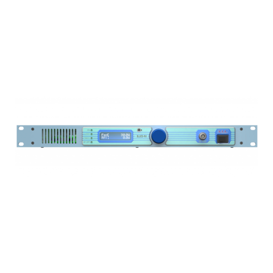
BLUES30/50NV ELETTRONICA 4.3 Frontal Panel Description [1] AIR FLOW Grid for the passage of the air flow of the forced ventilation. [2] ON Green LED, lit when the exciter is working or that is ready in RF power. [3] LOCK Green led, lit when the PLL is locked on the working frequency [4] F.BACK Yellow LED, lit when the foldback function is operating (automatic... -
Page 12: Rear Panel Description
BLUES30/50NV ELETTRONICA 4.4 Rear Panel Description [1] MAIN FUSE Fuse for mains supply. [2] MAINS Standard IEC connector for mains supply. [3] AIR FLOW Grid for the passage of the air flow of the forced ventilation. [4] R.F. OUT RF output connector, N-type. [5] RF TEST Not used. -
Page 13: Connectors Description
BLUES30/50NV ELETTRONICA 4.5 Connectors Description 4.5.1 Left (MONO) / Right / AES-EBU Type: XLR Female Positive Negative 4.5.2 Remote Type: DB15 Female Pin Name Type Meaning Interlock By passes power if closed to GND Ext AGC FWD Ext. signal,1÷12V, for power limitation (AGC) SDA IIC IIC communication serial data... - Page 14 BLUES30/50NV ELETTRONICA 4.5.6 LAN (option) Type: RJ45 female User Manual / 28 Rev. 1.0 - 29/11/16...
-
Page 15: Quick Guide For Installation And Use
The main fuse can be accessed from the outside on the rear panel. Extract the fuse carrier with a screwdriver to check its integrity or for replacement, if necessary. The fuse to be used is this type: Mains Fuse BLUES30NV (1x) 3.15A type 5x20 @ 90÷260 Vac BLUES50NV (1x) 6.3A type 5x20... - Page 16 BLUES30/50NV ELETTRONICA √ For operating tests only: dummy load with 50 Ohm impedance and adequate capacity (30/50W minimum). √ Connection cable kit including: • Mains power cable • Coaxial cable with BNC connectors for interlock signal connection • RF cable for output to load / antenna (50 Ohm coaxial cable with N-type connector) •...
- Page 17 BLUES30/50NV ELETTRONICA Note: the mains must be equipped with adequate earth connection properly connected to the equipment. This is a pre-requisite for ensuring operator safety and correct operation. Connect the audio and RDS/SCA signals from user’s sources to the transmitter input connectors.
-
Page 18: First Power-On And Setup
BLUES30/50NV ELETTRONICA 5.2 First power-on and setup Perform this procedure upon first power-up and each time you make changes to the configuration of the transmitter this component is integrated into. Note : Standard factory settings are RF output power off (Pwr OFF) and regulated output power set to upper limit (unless otherwise specified by customer). - Page 19 BLUES30/50NV ELETTRONICA The screen in edit mode will look like this: The bottom line gives the instantaneous power (50W in this example), to increase the level, turn to the right to turn to the left. Once you reach the desired level, press the ENCODER to confirm and exit to the default menu.
-
Page 20: Operation
BLUES30/50NV ELETTRONICA Input sensitivity: Input Figure 6.2 Trimmer Sensitivity Notes SCA1 [14] [15] - 8 ÷ +13 dBu Input level for 7,5 kHz overall deviation SCA2 [12] [13] - 8 ÷ +13 dBu (- 20 dB) [16] [17] -13 ÷ +13 dBu Left/ [18] [19]... - Page 21 BLUES30/50NV ELETTRONICA 1b) To modify power level setting, hold down the ENTER button until opening the power setup menu. The edit screen will look like this: Menu 2 The bottom line gives the instantaneous reading of the power (50W in this example), to increase the level rotate towards right, to reduce it rotate towards left.
-
Page 22: Management Firmware
BLUES30/50NV ELETTRONICA 5.4 Management Firmware The equipment features an LCD with two lines by 16 characters that displays a set of menus. The figure below provides an overview of equipment menus. The symbols listed below appear in the left portion of the display as appropriate: (Cursor) - Highlights selected (i.e. - Page 23 BLUES30/50NV ELETTRONICA The pressure of encoder when the display is switched on, while you are in the predefined menu (menu 1), serves in order to shown the following selection screen (menu 3) from which you can access to all the other menus: Menù...
- Page 24 BLUES30/50NV ELETTRONICA To edit an item, highlight the appropriate line and then press and hold the encoder until the command is accepted. This way, Pwr setting is toggled between On and Off and Mod setting is toggled between “x1” and “x10”. To edit the Power Good rate, simply select item “PgD”...
- Page 25 BLUES30/50NV ELETTRONICA 5.4.2 Power menu(Pwr) This screen shows the user the measures relating to the exciter RF power output: Menu 5 Visualization of the Forward Power. Visualization of the Reflected Power. Exit The entry allows to the user the prompt exit from current submenu and goes back to the predefined menu.
- Page 26 BLUES30/50NV ELETTRONICA goes back to the predefined menu. 5.4.4 Settings Menu (Set) This menu lets to read the working power to read and set the working frequency. Menù 7 Regulation of set up frequency. After having set a new frequency value, press the encoder to confirm the choice.
- Page 27 BLUES30/50NV ELETTRONICA Regulation of exchange time between digital and analog. Exit The entry allows to the user the prompt exit from current submenu and goes back to the predefined menu. 5.4.5 Miscellaneous Menu (Mix) This menu allows you to set the machine’s address in a serial bus connection (I type).
- Page 28 BLUES30/50NV ELETTRONICA Menu 9 Note that these are readings, rather than settings, and cannot be edited (note the empty arrow). Visualization of the software release. Visualization of the date release. Visualization of the release of the configurations table loaded in memory.
-
Page 29: Optional Functions
BLUES30/50NV ELETTRONICA 5.5 Optional Functions Optional functions can be added and/or modified for the equipment described in this manual. The available functions are carried in the continuation and can be requested to R.V.R. Elettronica at the moment of the order. 5.5.1 UP/DOWN Power Option The UP/DOWN Power modifies the function to receive signals present on the telemetry connector. -
Page 30: Identification Of The Modules
BLUES30/50NV ELETTRONICA 6. Identification of the Modules The BLUES30/50NV is made up of various modules linked to each other through connectors so as to make maintenance and any required module replacement easier. 6.1 Upper view The figure below shows the equipment upper view with the various components pointed out. -
Page 31: Working Principles
BLUES30/50NV ELETTRONICA 7. Principi di funzionamento A schematic view of the modules and connections making up the BLUES30/50NV with the telemetry board is shown in figure 7.1. INPUT (AES/EBU) AES/EBU BOARD FILTER R.F. R.F. INPUT OUTPUT (AUDIO/RDS) CONTROLLER P.A AMPLIFIER MAIN BOARD STEREO CODER PANEL CARD... -
Page 32: Main Board
BLUES30/50NV ELETTRONICA 7.3 Main Board The main board carries out the following functions: • Audio and SCA input treatment • Generation of carrier frequency • Modulation • R.F. amplification (Driver) 7.3.1 Audio input section The audio input section contains the circuits that perform the following functions: •... -
Page 33: Power Amplifier
BLUES30/50NV ELETTRONICA 7.4 Power amplifier The final power stage is enclosed in a totally shielded metal container fixed to the central part of the device. The RF signal coming from the main board reached the pilot, it come amplified and sent to the final stage which takes care of final amplification up to 30/50W. The amplifier is made in three stages. - Page 34 ______________________________________________________________________________ ______________________________________________________________________________ ______________________________________________________________________________ ______________________________________________________________________________ ______________________________________________________________________________ ______________________________________________________________________________ ______________________________________________________________________________ ______________________________________________________________________________ ______________________________________________________________________________ ______________________________________________________________________________ ______________________________________________________________________________ ______________________________________________________________________________ ______________________________________________________________________________ ______________________________________________________________________________ ______________________________________________________________________________ ______________________________________________________________________________ ______________________________________________________________________________ ______________________________________________________________________________ ______________________________________________________________________________ ______________________________________________________________________________ ______________________________________________________________________________ ______________________________________________________________________________ ______________________________________________________________________________ ______________________________________________________________________________ ______________________________________________________________________________...
- Page 35 ISO 9001:2000 certified since 2000 R.V.R Elettronica S.p.A. Via del Fonditore, 2 / 2c Zona Industriale Roveri · 40138 Bologna · Italy Phone: +39 051 6010506 · Fax: +39 051 6011104 e-mail: info@rvr.it ·web: http://www-rvr-it The RVR Logo, and others referenced RVR products and services are trademarks of RVR Elettronica S.p.A. in Italy, other countries or both. RVR ® 1998 all rights reserved. All other trademarks, trade names or logos used are property of their respective owners.
Need help?
Do you have a question about the BLUES30NV and is the answer not in the manual?
Questions and answers