Table of Contents
Advertisement
Quick Links
Advertisement
Table of Contents

Related Manuals for D-Link DVG‐6008G


Summary of Contents for D-Link DVG‐6008G
- Page 1 DVG‐6008G User Manual v1.1 ...
-
Page 2: Table Of Contents
4.5 Network Configuration ....................20 4.5.1 Local Network ..................... 20 4.5.2 ARP ........................21 4.5.3 VPN Parameter ....................21 4.6 Mobile Configuration ..................... 22 4.6.1 Basic Configuration .................... 22 Example: ........................24 Configuration between SMS box and gateway ..........24 _______________________________________________________________________________ D-Link Corporation 1 ... - Page 3 4.12 System Configuration ....................51 4.12.1 Service Parameter ................... 51 4.12.2 SIP Parameter ....................55 4.12.3 Port Parameter ....................61 4.13 Digit Map ........................63 4.14 Tools ..........................64 4.14.1 Firmware Upload ....................64 4.14.2 Syslog ........................ 65 _______________________________________________________________________________ D-Link Corporation 2 ...
- Page 4 5.5 How to trace ECC logs (Call Details) ................83 5.6 How to trace Module logs ..................... 83 6. The Way to Increase Antenna Isolation ................85 7. Frequency Asked Questions ....................88 8. Glossary ............................ 90 _______________________________________________________________________________ D-Link Corporation 3 ...
-
Page 5: Product Description
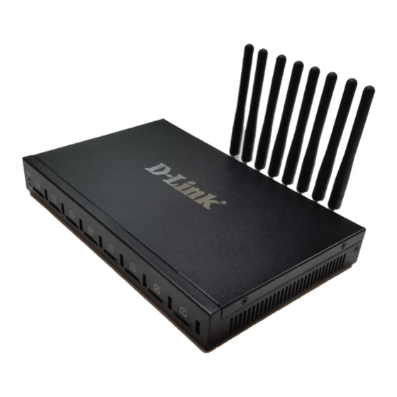
DVG-6008Gprovides high quality VoIP service which perfectly meets the requirement. This is a scenario shown as figure 1-2-1 Figure 1-2-1 Network scenario 1.3 Product Appearance The appearance of DVG-6008G shows as follow Figure 1-3-1 Front view of DVG-6008G _______________________________________________________________________________ D-Link Corporation 4 ... - Page 6 On: Power on Off: Power off Signal Signal strength indicators with green color Channel Use/Unuse indicator with Red color, ON is used, Off is unused SIM Slots SIM card slot Figure 1-3-2 Rear view of DVG-6008G _______________________________________________________________________________ D-Link Corporation 5 ...
- Page 7 Reset button to restore default IP and password or restore factory setting. Restore IP and Password: hold RST button3~5 seconds, RUN LED being ON during this time Restore factory setting: Hold RST button 7 seconds, RUN LED being blink _______________________________________________________________________________ D-Link Corporation 6 ...
-
Page 8: Functions And Features
Transportation environment: EN 300 019: Class 2.3 Acoustic noise: EN 300 753 CE EMC directive 2004/108/EC EN55022: 2006+A1:2007 EN61000-3-2: 2006, EN61000-3-3: 1995+A1: 2001+A2: 2005 EN55024: 1998+A1: 2001+A2: 2003 Certifications: FCC, CE _______________________________________________________________________________ D-Link Corporation 7 ... -
Page 9: General Hardware Specification
DVG-6008G VoIP Gateway User Manual 1.4.4 General Hardware Specification Power Supply Input: 100-240V, 50-60Hz Temperature(Operation): 0 ℃ ~ 45 ℃ (Storage): -20 ℃ ~80 ℃ Operation Humidity: 10%-90% No Condensation _______________________________________________________________________________ D-Link Corporation 8 ... -
Page 10: Installation Guide
For Wireless part,make sure antennas connecting well on device. Inserting SIM cardsand GSM channels should work properly. 2.2 Installation Procedure 2.2.1 Install SIM Card Figure 2-2-1 SIM Card installation 2.2.2 Antenna Installation Figure 2-2-4 Antenna Installation _______________________________________________________________________________ D-Link Corporation 9 ... -
Page 11: Network Cable Connection Of Equipment
DVG-6008G VoIP Gateway User Manual 2.2.3 Network Cable Connection of Equipment Figure 2-2-5DVG-6008G networkconnection _______________________________________________________________________________ D-Link Corporation 10 ... -
Page 12: Basic Operation
Press RST button about 3 seconds then reboot gateway. The IP address, username and password will be back to factory default. 3.2.4 Restore factory setting Press RST button about 7 seconds then reboot gateway then it will restore to factory setting. 3.2.5 Console port access _______________________________________________________________________________ D-Link Corporation 11 ... -
Page 13: Web Interface Configuration
Figure 4-1-1 WEB log interface Enter username and password and then click “OK” in configuration interface. The default username and password are “admin/admin”. It is strongly recommended, change the default password to a new password for system security. _______________________________________________________________________________ D-Link Corporation 12 ... -
Page 14: Parameters Configuration
Go through navigation tree, user can check, view modify, and set the device configuration on the right of configuration interface. 4.3System Information System information interface shows the basic information of status information, Mobile information and SIP information. 4.3.1 System Information Figure 4-3-1 system Information Table 4.3-1 System Information _______________________________________________________________________________ D-Link Corporation 13 ... -
Page 15: Mobile Information
Displays DNS server IP address in the same network with the gateway A unique device ID which assigned in factory. This device ID to be used as Device ID register ID with D-Link SIM cloud. Its indicates communicate status with SIMCloud server, there are two type of status:... - Page 16 Show the Status of port, include idle, active, alert and processing Idle means there is no call on this channel Call Status Processing means call is connecting Alerting means destination is ringing Active means the call is connected _______________________________________________________________________________ D-Link Corporation 15 ...
-
Page 17: Sip Information
Shows the registration status of VoIP channel, including registered Register Status and unregistered. Status Show the status of port, Include "onhook" and "offhook" 4.4 Statistics 4.4.1 TCP/UDP Figure 4-4-1 TCP/UDP Statistics 4.4.2 RTP Figure 4-4-2 RTP _______________________________________________________________________________ D-Link Corporation 16 ... -
Page 18: Sip Call History
The amount of incoming calls which have connected connected Incoming Answered The amount of incoming calls which answered by GSM/CDMA module Incoming Failed The amount of incoming calls which failed Outgoing The amount of outgoing calls which attempted to IP side Attempted _______________________________________________________________________________ D-Link Corporation 17 ... -
Page 19: Ip To Gsm Call History
Figure 4-4-5CDR Report It is support 10000 CDRs on gateway. The CDRs will lost after reboot while save CDR set to No. To make the device works in good performance,we are strongly recomand to set ’Save _______________________________________________________________________________ D-Link Corporation 18 ... -
Page 20: Auto Lock Bcch History
Call duration of the call RTP send/recv/loss rate RTP Statistics of the call 4.4.6 Auto Lock BCCH History Figure 4-4-6 Auto Lock BCCH History It is record history of BCCH to help analysis SIM card register status. _______________________________________________________________________________ D-Link Corporation 19 ... -
Page 21: Network Configuration
When enable the WAN port option of "Obtain DNS Server Address Server Address Automatically”, which will be enabled subsequently. Automatically Use the Following DNS Fill in the IP address of "Primary DNS Server" and "Secondary DNS Server Server" Addresses _______________________________________________________________________________ D-Link Corporation 20 ... -
Page 22: Arp
ARP entries to: Protect your network against ARP spoofing Prevent network confusion as a result of misconfigured network device Figure 4-5-3 Add ARP Click Search Allto check ARP buffer. 4.5.3VPN Parameter Figure 4-5-3 VPN Parameter _______________________________________________________________________________ D-Link Corporation 21 ... -
Page 23: Mobile Configuration
Follow VPN setting, can be null Encryption parameter, support 40/128 bit, must be match with VPN Use MPPE server Check VPN connecting status on system information 4.6 Mobile Configuration 4.6.1 Basic Configuration Figure 4-6-1Basic Configuration Table 4-6-1 Description of Basic Configuration _______________________________________________________________________________ D-Link Corporation 22 ... - Page 24 To adjust voice quality level possibly help to improve low ASR issue but may affect voice quality. Abnormal Call It is an optional parameter to handle abnormal calls. handle Notes: please reference API document for more details. _______________________________________________________________________________ D-Link Corporation 23 ...
-
Page 25: Example
The IP server which installed SMS box software is 172.16.221.221, pre-set Port12000, User ID aabbcc and password abc123 as example. Configure SMS box (Next Page) Then click OK and start service, the gateway IP will be presented in device list of SMS box _______________________________________________________________________________ D-Link Corporation 24 ... -
Page 26: How To Configure Abnormal Call On Gateway
10times fail to call to mobile network continuously Mobile Operate reset module to register again to mobile network. Block means won’t call out via this module any more unless unblock it 4.6.2Mobile Configuration Figure 4-6-2 Mobile State _______________________________________________________________________________ D-Link Corporation 25 ... - Page 27 SIM card number of the channel. That must be configured when “Forward” function enable. Step Step length value range is 1-120 s, step length multiplied by time of single call just said a single call duration time allowed. _______________________________________________________________________________ D-Link Corporation 26 ...
- Page 28 No. of the SIM/UIM card is recommended to use as the port description for alarm, or any other string. Remain Time Indicates the current SIMremain time. It can’t modified Restore time Recovers the SIM remain time to initial value, the Maximum Call Duration. _______________________________________________________________________________ D-Link Corporation 27 ...
-
Page 29: How To Configure Maximum Call Limitation
So we have to configure maximum call duration as below: Step = Cu = 6s Maximum Call Duration = total call minutes of SIM (minutes) * 60s / step = Ct *60 / Cu = 1200 *60 / 6 =12000 step _______________________________________________________________________________ D-Link Corporation 28 ... -
Page 30: Pin Management
This configurable option is used in a situation that the SMSC number could not detected by celluar module. When such case happens, please contact with mobile service provider to identify the SMSC number and then add SMSC number in SMSC configurable web interface. _______________________________________________________________________________ D-Link Corporation 29 ... -
Page 31: Send Sms/Recv Sms
USSD (Unstructured Supplementary Service Data) is a Global System for Mobile(GSM) communication technology that is used to send text between a mobile phone and an application program in the network. Applications may include prepaid roaming or mobile chatting. Figure 4-6-7 USSD _______________________________________________________________________________ D-Link Corporation 30 ... -
Page 32: Carrier
There are two modes to select carrier automatic and manual. Automatic mode can be automatically search operators. Manual mode can choose operators from the carrier list. Carrier List If you select manual mode, you can select carrier from carrier list. _______________________________________________________________________________ D-Link Corporation 31 ... -
Page 33: Bcch
(BCCH) is a point to multipoint, BCCH unidirectional (downlink) channel used in the Um interface of the GSM cellular standard Receive Level Receiving signal strong strength Choose a frequency to lock the operations. _______________________________________________________________________________ D-Link Corporation 32 ... -
Page 34: Call Forwarding
Description Local To use local SIM card which install on gateway, this way is most common used by many of users SIMBox SIM Box is a small box which use for SIM card storage. It ideal _______________________________________________________________________________ D-Link Corporation 33 ... -
Page 35: Cloud Server
Compare to SIM Box, SIM Bank is most powerful and provide flexible SIM management rules such as SIM Rotation, SIM switching and anti-block policy. It is important component of D-Link SIM cloud solution. With SIM Bank, GSM gateways can be deployed in different locations and countries so that the userare able to supervise all SIMs in one place. -
Page 36: Routing Configuration
Device S/N is the device ID on gateway, find it on the page system information, as below: 4.7 Routing Configuration 4.7.1 Routing Parameter Figure 4-7-1 Routing Parameter Table 4-7-1Description of Routing Parameter Parameters Description Tel->IP Parameter Global parameters, it will take effect while number manipulation configured _______________________________________________________________________________ D-Link Corporation 35 ... -
Page 37: Ip->Tel Routing
All the called number must match the destination prefix, the call prefix indicates the connected number Destination Prefix Any: include anonymous, 0xxxx, 1[2-9]xxxx etc. 0xxxx: consist of some digits such as 015,08,09 1[3-8]6:consist of some prefix, include 136,146,156,166,176, 186 _______________________________________________________________________________ D-Link Corporation 36 ... -
Page 38: Tel->Ip Routing
Any: include anonymous, 0xxxx, 1[2-9]xxxx etc. 0xxxx: consist of some digits such as 015,08,09 1[3-8]6:consist of some prefix, include 136,146,156,166,176, 186 Destination Its specifies destination IP trunk or SIP server Figure 4-7-4 Tel to IP routing Modify _______________________________________________________________________________ D-Link Corporation 37 ... - Page 39 31<Unicom> will match the prefix ”x.”, ”x.” is a wildcard string which will match any prefix except ”anonymous” calls. Meanwhile sending the calls destination IP 13<eia> if called number match with destination prefix ”00”. Figure 4-7-6 Tel to IP routing Modify _______________________________________________________________________________ D-Link Corporation 38 ...
-
Page 40: Manipulaton Configuration
Figure 4-8-1 IP->Tel destination numbers manipulation Table 4-8-1 Description of IP->Tel destination numbers manipulation Parameters Description IP->Tel destination It is an optional configuration item, and is used to add a rule for numbers changing number manipulation _______________________________________________________________________________ D-Link Corporation 39 ... - Page 41 Add the new digits in front of the original number Suffix to Add Add the new digits at the end of the original number Add an IP->Tel Manipulation, to change the called number from 2547888888 to 07888888 Figure 4-8-2 IP->Tel destination numbers manipulation _______________________________________________________________________________ D-Link Corporation 40 ...
-
Page 42: Tel->Ip Source Numbers
IP->Tel routing. It uniquely identifies a route. Its value is assigned globally, ranging Index from 0 to 31. It describes the rule for the ease of identification. Its value is Description character string _______________________________________________________________________________ D-Link Corporation 41 ... - Page 43 Number of Digits to It specifies the number of Digits to Leave from Right Leave from Right Example Add aTel->IP Manipulation, to change the caller number to 07888888 Figure 4-8-4 Tel ->IP destination numbers source manipulation add _______________________________________________________________________________ D-Link Corporation 42 ...
-
Page 44: Tel->Ip Destination Numbers
The Tel-IP Manipulation numbers defined the rules of add, and deletion of called numbers, which are manipulation referenced by Tel->IP routing. It uniquely identifies a route. Its value is assigned globally, ranging Index from 0 to 31. _______________________________________________________________________________ D-Link Corporation 43 ... - Page 45 Number of Digits to It specifies the number of Digits to Leave from Right Leave from Right Example Add a Tel->IP Manipulation rule, to change the called number from 1111 to 0751111 Figure 4-8-6 Tel->IP destination numbers manipulation _______________________________________________________________________________ D-Link Corporation 44 ...
-
Page 46: Operation
IP and IP Group send calls to certain IP->Tel Operation numbers. It includes: forbid call, call allowance, auto call, and password authentication. It uniquely identifies a route. Its value is assigned globally, ranging Index from 0 to 31. _______________________________________________________________________________ D-Link Corporation 45 ... - Page 47 07 are not allowed call out. The calls match this rule will be rejected by gateway. Index 29: define a rule for IP 17<FreeSentral> that all the calls must go with valid password authentication. _______________________________________________________________________________ D-Link Corporation 46 ...
-
Page 48: Tel->Ip Operation
All the caller number must match the source prefix. It specifies the source prefix allow to send call out Source Prefix Any: include anonymous, 0xxxx, 1[2-9]xxxx etc. 0xxxx: consist of some digits such as 015,08,09 1[3-8]6:consist of some prefix, include 136,146,156,166,176, 186 _______________________________________________________________________________ D-Link Corporation 47 ... - Page 49 How to route incoming call to DID or IVR automatically? Step1:System Configuration-> Port Configuration to configure VoIP hotline number, this hotline number can be DIDs, access code and extension etc. Step2: Operation-> Tel->IP Operation to add a new rule: _______________________________________________________________________________ D-Link Corporation 48 ...
-
Page 50: Port Group Configuration
Add remote IP of Softswitch, SIP server which will send call traffics to IP Trunk gateway. It uniquely identifies a trunk. Its value is assigned globally, ranging from Index 0 to 31. It describes the trunk for the ease of identification. Its value is character Description string _______________________________________________________________________________ D-Link Corporation 49 ... -
Page 51: Ip Trunk Group
It describes the route for the ease of identification. Its value is Description character string It specifies the IP will add to IP group Example To add an IP group, set IP “10, 14, 17” to IP group 18 Figure 4-11-4 IP Trunk group modify _______________________________________________________________________________ D-Link Corporation 50 ... -
Page 52: System Configuration
Enable the "silence suppression" almost no impact on call quality, and can save about half of the bandwidth; Call Progress Tone Each country has its different call progress tone required standards, such as busy tone, ring back tones and ring tone standards, users can select the area standard _______________________________________________________________________________ D-Link Corporation 51 ... - Page 53 Enable Auto Outgoing Routing Means when call out, whether by ordinal or polling pick to Select a Channel, this feature are generally used when use the same SIP User ID to register. IP to PSTN One Stage Dialing _______________________________________________________________________________ D-Link Corporation 52 ...
- Page 54 "; if set to No, the device will play dial tone instead of voice prompt. RTP Detect This option is todisconnect call when there is no RTP received. Default value is 90s Configure DTMF and NAT Traversal _______________________________________________________________________________ D-Link Corporation 53 ...
- Page 55 Default is No. All calls will be rejected except calls from SIP server. IP Trunk will not work when this option enabled. Allow Call from PSTN to IP without Registration Refer to "SIP Configuration" -> "Is register”. If "Is register"setting is no, this option _______________________________________________________________________________ D-Link Corporation 54 ...
-
Page 56: Sip Parameter
Default is No. if it set to Yes, the gateway will send SIP OPTION periodic to check health status between gateway and SIP server. Outbound Proxy Outbound proxy, it mainly used in firewall / NAT environment. That make the _______________________________________________________________________________ D-Link Corporation 55 ... - Page 57 Use the separate SIP port Each channel has separate SIP port so that they could be handle SIP call separately. After Use Same Local SIP Port set to No The Local SIP port will be changed on Port Parameter page. _______________________________________________________________________________ D-Link Corporation 56 ...
- Page 58 The DNS query type defines the type of information that will be requested from DNS server DNS refresh interval The interval of DNS refresh, Range from 0 to 60000 mins, 0 means disable default value is disable. Configuring SIP Timers _______________________________________________________________________________ D-Link Corporation 57 ...
- Page 59 Call-ID: 8874a4e49f11af243c6b717c05a16e35@172.16.222.22 CSeq: 1804289386 OPTIONS Contact: <sip:31@172.16.222.22> Max-Forwards: 70 Accept: application/sdp Content-Length: 0 Keepalive Retry Count This field specifies re-transmission times for OPTION message. Its value range from 1-10 times. Configuring Caller ID and 183 Mode _______________________________________________________________________________ D-Link Corporation 58 ...
- Page 60 SIP Session Timer is a keep alive mechanism for SIP sessions that allow User Agents (UA) or proxies to determine the status of a session and to release it if it is not active, even if a BYE has not been received. _______________________________________________________________________________ D-Link Corporation 59 ...
- Page 61 Route: sips:p1.atlanta.example.com;lr Supported: timer Session-Expires: 4000;refresher=uac Max-Forwards: 70 To: Bob <sips:bob@biloxi.example.com>;tag=9as888nd From: Alice <sips:alice@atlanta.example.com>;tag=1928301774 Call-ID: a84b4c76e66710 CSeq: 314162 UPDATE Contact: <sips:alice@pc33.atlanta.example.com> Configuring GSM-SIP Mapping Code This part specifies response codes between GSM cause reasonand SIP response code. _______________________________________________________________________________ D-Link Corporation 60 ...
-
Page 62: Port Parameter
SIP Response, the SIP server possibly need some specific SIP response from the gateway. Example, SIP server need SIP response 180 Ringing instead of 183 Ringing, the configuration should be as below: 4.12.3 Port Parameter Figure 4-12-3 Port List Figure 4-12-4 Port Configuration _______________________________________________________________________________ D-Link Corporation 61 ... - Page 63 To PSTN Hotline number. Leave it blank if you don’t need this function. *Note: Please configureIP->Tel Operation if you need this function. Auto-Dial Delay Time The auto-dial delay time of hotline , the range is 0-10 seconds _______________________________________________________________________________ D-Link Corporation 62 ...
-
Page 64: Digit Map
+: Match 1 or more times. 9. Modifiers ?: Match 0 or 1 times. Example: Assume we have the following digit maps: 1. xxxxxxx | x11 and a current dial string of "41". Given the input "1" the current dial _______________________________________________________________________________ D-Link Corporation 63 ... -
Page 65: Tools
01/02 is vendor name 22/23 is hardware version, 02.22.xx.xx and 02.23.xx.xx means they had different hardware version xx-xx is version number Step 3. Upload firmware, select the package from specific folder on the computer and click Upload button. _______________________________________________________________________________ D-Link Corporation 64 ... -
Page 66: Syslog
There are 5 levels of syslog, Including NONE, DEBUG, NOTICE, WARNING and ERROR. The Signal Log is include following traces which defined in system by default SD, hardware debug SIP, SIP signaling trace STUN, STUN logs _______________________________________________________________________________ D-Link Corporation 65 ... -
Page 67: Filelog /Filelog Download
4.14.3 Filelog /Filelog Download The main difference between Filelog and syslog is, Filelog stores in local internal memory but syslog output external server. The log contents are the same as syslog. 4.14.4 Management Parameter Figure 4-14-2 Management Parameter _______________________________________________________________________________ D-Link Corporation 66 ... -
Page 68: Config Backup
User need to fill the NTP Server Address and select Time Zone Web Port Default is 80 Telnet Port Default is 23 4.14.5Config Backup Figure 4-14-3 Data backup Click 'Backup' to download configuration file to your computer. 4.14.6 Config Restore Figure 4-14-4 Config Restore _______________________________________________________________________________ D-Link Corporation 67 ... -
Page 69: Ivr Voice Prompt Upload
Ping is utility used to test the reach ability of a host on an Internet Protocol (IP) network and to measure the round-trip time for messages sent from the originating host to a destination host. Figure 4-14-6 Ping Test _______________________________________________________________________________ D-Link Corporation 68 ... -
Page 70: Tracert Test
Tracert is a computer network diagnostic tool for displaying the route (path) and measuring transit delays of packets across an Internet Protocol (IP) network. Figure 4-14-7 Tracert Test 4.14.10 Network Capture Network capture is a very important diagnostic tool for maintenance. This section is describes _______________________________________________________________________________ D-Link Corporation 69 ... - Page 71 Save the capture file to local computer The capture is named to ‘capture(x).pcap’, x is serial number of capture and will be added 1 in next time. The sample of PCM capture as below: Getting start to Syslog capture _______________________________________________________________________________ D-Link Corporation 70 ...
- Page 72 Getting start to RTP capture PCM capture is help to analysis voice stream between gateway and remote IPPBX/SIP Server. To enable RTP capture: Select RTP special on Network Capture page Click Start to enable RTP capture _______________________________________________________________________________ D-Link Corporation 71 ...
- Page 73 Click Stop to disable DSP capture Save the capture to local computer The capture is named to ‘capture(x).pcap’, x is serial number of capture and will be added 1 in next time. The sample of RTP capture as below: _______________________________________________________________________________ D-Link Corporation 72 ...
-
Page 74: Voice Loopback Test
Voice Loopback test should be done on call status. Each call can do one kind of test. After each test, please hang up and call again, refresh web interface and go on the other tests. Voice stream patch on gateway: _______________________________________________________________________________ D-Link Corporation 73 ... -
Page 75: Username & Password
Click DSP IP Testto start test Check the voice on both sides. GSM side become silence and echo should be generated on IPPHONE side Hangup 4.14.13Username &Password Figure 4-14-13Username and Password _______________________________________________________________________________ D-Link Corporation 74 ... -
Page 76: Factory Reset
4.14.14 Factory Reset Figure 4-14-14 Factory Reset Be careful do this operation, after restore factory setting, all the parameters will be changed to the factory default. 4.14.15 Restart Figure 4-14-15 Restart _______________________________________________________________________________ D-Link Corporation 75 ... -
Page 77: Troubleshooting And Command Line
5. Troubleshooting and Command Line 5.1 Login DVG & General Knowledge of DWG Command This is a document for some customers who need more details of D-LINK’s products with command lines. To make sure the system runs successfully, we suggest customers setting DWG by GUI. -
Page 78: Summarize Of Commands In "Ros#" Mode
5.2.1 Summarize of commands in "ROS#" mode Input "?" to get the information of all commands in "ROS#" mode. 5.2.2 General Purpose Commands in "ROS#" mode Show IP address (show int) Show Time(show clock) Show version (show version) _______________________________________________________________________________ D-Link Corporation 77 ... -
Page 79: Show Sip Information(Show Sip Config)
DVG-6008G VoIP Gateway User Manual Show sip Information(show sip config) _______________________________________________________________________________ D-Link Corporation 78 ... -
Page 80: Show Memory Status (Show Memory Detail)
DVG-6008G VoIP Gateway User Manual Show memory status (show memory detail) Show SIP port status (show sip all) Show Current calls (sh ecc call) _______________________________________________________________________________ D-Link Corporation 79 ... -
Page 81: Show Rtp Session ( Sho Rtp Se)
DVG-6008G VoIP Gateway User Manual Show RTP session ( sho rtp se) Show ASR/ACD statistics (show ecc state) 5.3 Commands in "Config" Mode 5.3.1 Summarize of commands in "config" mode Input "^config" in the "ROS# " to enter "config" mode. _______________________________________________________________________________ D-Link Corporation 80 ... -
Page 82: General Purpose Commands In "Config" Mode
DVG-6008G VoIP Gateway User Manual Input "?" to show the all commands and its information. 5.3.2 General Purpose Commands in "Config" mode Set time (clock set) _______________________________________________________________________________ D-Link Corporation 81 ... -
Page 83: Save The Configuration (Save)
Enable SIP debug (deb sip msg all) 5.4How to trace SIP logs Create telnet session to gateway, the main steps as below: Welcome to Command Shell! Username:admin Password:***** ROS>en ROS# ROS#^config ROS(config)#deb sip msg all ROS(config)#ex _______________________________________________________________________________ D-Link Corporation 82 ... -
Page 84: How To Trace Ecc Logs (Call Details)
ROS(config)#no deb port all ROS(config)# ROS(config)#ex ROS#^ada ROS(ada)#ADA CONNECTED ...,WELCOME! ROS(ada)#turnon 84 Disable trace: ROS(ada)#turnoff 84 5.6 How to trace Module logs Welcome to Command Shell! Username:admin Password:***** ROS>en ROS#^ada ROS(ada)#ADA CONNECTED ...,WELCOME! ROS(ada)#cmd 53 19 _______________________________________________________________________________ D-Link Corporation 83 ... - Page 85 DVG-6008G VoIP Gateway User Manual // enable trace. 0means port range 0 to 0, means port range from 0 to 8; means enable module trace ROS(ada)#cmd 53 19 disable module trace _______________________________________________________________________________ D-Link Corporation 84 ...
-
Page 86: The Way To Increase Antenna Isolation
Put a metal shielding baffle between antennas, which can help to prevent radiation signal coupling from each other. If the metal baffle is big enough, the isolation will be unlimited big in theory. Figure 6.2 Isolation by metal shielding baffles _______________________________________________________________________________ D-Link Corporation 85 ... - Page 87 Figure 6.3 Isolation by antenna orthogonal polarization In theory, the isolation is unlimited big if the polarization is really orthogonal, like vertical polarization VS horizontal antenna; RHCP (Right Hand CircularPolarization) VS LHCP (Left Hand Circular Polarization). _______________________________________________________________________________ D-Link Corporation 86 ...
- Page 88 In real practical application, the antenna are all elliptic polarization, they have a certain ratio. So putting the same type antennas in orthogonal position will be helpful for isolation. 6.4 Isolate by antenna radiation pattern Radiation pattern of low directivity antenna radiation pattern of high directivity antenna _______________________________________________________________________________ D-Link Corporation 87 ...
-
Page 89: Frequency Asked Questions
2) Make sure the connected network devices (router, switch or hub) support 10M/100M adaptive, if not, connect the Equipment directly to PC, landing WEB and in the "local connection" Configuration interface Select the correct Ethernet Work Mode; _______________________________________________________________________________ D-Link Corporation 88 ... - Page 90 (it is a special equipment, not afraid of virus attacks); (2) try to enable the equipment tunnel (through the WEB for Configuration, Also, please NOTE, open the tunnel will impact voice quality, Please do not enable the tunnel as far as possible, refer WEB _______________________________________________________________________________ D-Link Corporation 89 ...
-
Page 91: Glossary
4) Make sure the LAN equipment is working, user can try to restart the gateway or router to solve the problem 5) Check whether there is more than one D-LINK series products in LAN network: some gateways or routers, processing network packet is vulnerable (for example, to multiple network devices or the same protocol network communication, NAT allocated the same conversion communications Channel). - Page 92 DVG-6008G VoIP Gateway User Manual CID:Cell ID BTS: Base Transceiver Station DTMF:Dual-Tone Multifrequency IVR:Interactive Voice Response NAT: Network Address Translation RTP: Real-time Transport Protocol VoIP: Voice over IP _______________________________________________________________________________ D-Link Corporation 91 ...
Need help?
Do you have a question about the DVG‐6008G and is the answer not in the manual?
Questions and answers