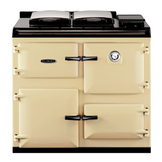
Summary of Contents for AGA RAYBURN Heatranger 480CD
- Page 1 Servicing Instructions Heatranger 480CD For use in GB and IE DESN 514712 PLEASE READ THESE INSTRUCTIONS BEFORE SERVICING THIS APPLIANCE raywarranty@aga-web.co.uk 01/07A EINS 514874...
-
Page 2: Table Of Contents
Contents SECTION CONTENTS PAGE CONSUMER PROTECTION HEALTH & SAFETY ANNUAL SERVICING SERVICING SERVICE SCHEDULE PRE-SERVICE CHECK COMBUSTION AIR HOTPLATE CLEANING BURNER CHAMBER/SERVICING PREPARATION COOKER BURNER SERVICING BURNER ACCESS PARTS TO BE REMOVED TO WITHDRAW COOKER BURNER BOILER SERVICE BOILER SERVICING REPLACEMENT OF IONSIATION PROBE REPLACEMENT OF PARTS REPLACEMENT OF ELECTRODE... -
Page 3: Consumer Protection
IMPORTANT NOTICE: PLEASE READ THE ACCOMPANYING WARRANTY Any alteration that is not approved by Aga could invalidate the approval of the appliance, operation of the warranty and could affect your statutory rights. -
Page 4: Annual Servicing
Servicing ANNUAL SERVICING SERVICE SCHEDULE It is important for the current operation of the appliance 1. Carry out a pre-service check noting any operational that servicing be carried out annually by a professional or faults. competent person in accordance with gas safety regulations. -
Page 5: Pre-Service Check
Servicing PRE-SERVICE CHECK Operate the appliance and system, noting any faults which may need to be corrected during service. COMBUSTION AIR Check that CO levels are within tolerance see Technical Specification Fig. 1 in the Installation Instructions. If these levels cannot be obtained, check gas rate and adjust the throttle screw if required and allow readings to stabilise. -
Page 6: Preparation
Cooker Burner Servicing PREPARATION WARNING: BEFORE REMOVING SERVICE ACCESS COVERS OR THE BURNERS ENSURE THAT ALL ELECTRICAL SUPPLIES TO THE APPLIANCE HAVE BEEN ISOLATED. BURNER ACCESS SEE FIG. 3 1. Open up the bottom door access door. Remove door and put in a safe place. 2. -
Page 7: Boiler Service
Boiler Servicing Once adjustment has been made, wait until the CO level BOILER SERVICE stabilises and recheck the combustion. Repeat the above steps as necessary. CONDENSATE TRAP SERVICE After completion of calibration, recheck the CO maximum output. It is also advisable to check the gas Unscrew condensate trap base and check for excessive capacity at the metre against the figures given in the deposits. -
Page 8: Replacement Of Ionsiation Probe
Replacement of Parts (Electrical Controls) REPLACEMENT OF IONISATION PROBE SEE FIG. 8 1. Turn off power to the appliance. 2. Unscrew the fixing screw and withdraw probe. 3. Replace probe, ensuring both the gasket and spark return are also fitted. FIG. -
Page 9: Control Board Replacement
Replacement of Parts (Electrical Controls) CONTROL BOARD REPLACEMENT SEE FIGS. 10 & 11 1. Remove plinth. 2. Unscrew 2 bolts fixing the board to the base. 3. Move the terminal strip and bracket to allow removal of the main PCB. 4. - Page 10 Replacement of Parts (Electrical Controls) FIG. 12 DESN 514884...
-
Page 11: To Fit New Display Panel And Cooker Thermistor
Replacement of Parts (Cooker) TO FIT NEW DISPLAY PANEL & COOKER THERMISTOR SEE FIG. 13 & 14 1. Remove glass front facia by unscrewing buttons and removing 2 M5 screws. 2. Pull off control knobs and remove glass. 3. Undo 4 screws on the chassis and remove from front plate ensuring electrical connector is disconnected. - Page 12 Replacement of Parts (Boiler Burner) FIG. 15 DESN 514889...
-
Page 13: Removal And Replacement Of Boiler Fan
Replacement of Parts (Boiler Burner) REMOVAL AND REPLACEMENT OF BOILER FAN 1. Close boiler gas cock. 2. Unscrew boiler gas inlet. (See Fig. 17). 3. Remove 3 M6 nuts from boiler manifold. (See Fig. 17) 4. Unscrew boiler gas valve connections and remove gas train. -
Page 14: To Fit New Burner
Replacement of Parts (Boiler Burner) TO FIT NEW BURNER SEE FIG. 20 1. Remove manifold and fan as shown previously. 2. The burner can now be simply pulled out. FIG. 20 DESN 514894 TO FIT NEW IGNITOR, IONISATION PROBE AND OVERHEAT SEE FIG. -
Page 15: Overheat Stat Removal
Replacement of Parts (Boiler Burner) OVERHEAT STAT REMOVAL SEE FIG. 23 1. Disconnect 2 flag connectors from the stat. 2. Unscrew overheat and remove. FIG. 23 DESN 514898 REMOVAL OF HEAT EXCHANGER ACCESS PANEL AND CLEANING SEE FIG. 24 1. Unscrew 4 x M6 nuts. 2. -
Page 16: Replacement Flow/Return Sensor And
Replacement of Parts (Boiler Burner) REPLACEMENT FLOW/RETURN SENSOR & WATER PRESSURE SWITCH SEE FIG. 25 & 26 1. To replace the flow and return sensor disconnect the electrical connection and then unclip from the pipe. (See Fig. 25). 2. To replace the water pressure switch, the system must first be drained. -
Page 17: Fault Diagnostics
Fault Diagnostics... - Page 18 Fault Diagnostics...
- Page 24 For further advice or information contact your local distributor/stockist With Aga’s policy of continuous product improvement, the Company reserves the right to change specifications and make modifications to the appliance described at any time. Manufactured by Station Road Ketley Telford...


Need help?
Do you have a question about the RAYBURN Heatranger 480CD and is the answer not in the manual?
Questions and answers