Table of Contents
Advertisement
Quick Links
Advertisement
Table of Contents

Related Manuals for Genie CCTV V1.0 H.264 MDVR4SD

Summary of Contents for Genie CCTV V1.0 H.264 MDVR4SD
- Page 1 H.264 4Channel Mobile DVR User Manual - V1.0 MODEL: MDVR4SD www.geniecctv.com...
- Page 2 2009 Genie CCTV Limited All rights reserved. This material, information and instructions for use contained herein are the property of Genie CCTV Ltd. No part of this manual, including the products and software described in it, may be reproduced, transmitted, transcribed,...
-
Page 3: Package Contents
PACKAGE CONTENTS Prior to installation of this MDVR4SD DVR, please verify that the packaging contains the following contents: 1. One DVR 2. One AC Adaptor 3. One Power Cable 4. One Remote Controller 5. DVR Viewer Program CD 6. Instruction Manual on CD 7. -
Page 4: Risk Of Electrical Shock Warning
RISK OF ELECTRICAL SHOCK WARNING WARNING TO REDUCE THE RISK OF FIRE OR ELECTRIC SHOCK, DO NOT EXPOSE THIS PRODUCT TO RAIN OR MOISTURE. DO NOT INSERT ANY METALLIC OBJECTS THROUGH THE VENTILATION GRILLS OR OTHER OPENINGS ON THE EQUIPMENT. CAUTION EXPLANATION OF GRAPHICAL SYMBOLS The lightning flash with arrowhead symbol, within an equilateral triangle, is intended to... -
Page 5: Trademark Acknowledgements
DISCLAIMER While every effort has been made to ensure that the information contained in this guide is accurate and complete, no liability can be accepted for any errors or omissions. Maker reserves the right to change the specifications of the hardware and software described herein at any time without prior notice. -
Page 6: Read This First
Read this First Test Sessions Before you attempt to record important subjects, we highly recommend that you have several test sessions to ensure that the Digital Video Recorder is operating and being operated correctly. Please note that Maker, its subsidiaries and affiliates, and its distributors are not liable for any consequential damages arising from any malfunction of the Digital Video Recorder or its accessories. -
Page 7: Safety Precautions
SAFETY PRECAUTIONS Before using the Digital Video Recorder, please ensure that you read and understand the safety precautions described below. Always ensure that the Digital Video Recorder is operated correctly. The safety precautions noted on the following pages are intended to instruct you in the safe and correct operation of the Digital Video Recorder and its accessories to prevent injuries or damage to the self, other persons and equipment. - Page 8 Do not allow the equipment to come into contact with, or become immersed in, water or other liquids. Do not allow liquids to enter the interior. The Digital Video Recorder has not been waterproofed. If the exterior comes into contact with liquids or salt air, wipe it dry with a soft, absorbent cloth. In the event that the water or other foreign substances enter the interior, immediately turn the Digital Video Recorder’s Power off or unplug the power cord from the power outlet.
- Page 9 PREVENTING MALFUNCTIONS Avoid Strong Magnetic Fields. Never place the Digital Video Recorder in close proximity to electric motors or other equipment generating strong electromagnetic fields. Exposure to strong magnetic fields may cause malfunctions or corrupt image data. Avoid Condensation Related Problems. Moving the equipment rapidly between hot and cold temperatures may cause condensation (water droplets) to form on its external and internal surfaces.
-
Page 10: Table Of Contents
Table of Contents ABOUT THIS MANUAL ..............13 FEATURES & SPECIFICATIONS ..........13 2.1 Features ....................... 14 2.2 Specifications ....................15 OVERVIEW & CONTROLS............18 3.1 Front Panel ..................... 18 3.2 Rear View..................... 19 3.3 IR REMOTE CONTROLLER ............... 20 3.3 MOUSE CONTROLLER ................ - Page 11 5.3 RECORD...................... 37 5.3.1 RECORD SETUP ......................37 5.3.2 RECORD PROGRAM.....................38 5.3.3 PREVIEW QUALITY.......................38 5.3.4 AUDIO RECORD......................39 5.3.5 REPEAT RECORD ......................39 5.3.6 HOLIDAY ........................40 5.3.7 RECORD LIMIT......................40 5.4 EVENT ......................41 5.4.1 MOTION DETECTION....................41 5.4.1.1 CHANNEL ........................... 41 5.4.1.2 SENSITIVITY ..........................42 5.4.1.3 AREA SETUP..........................
- Page 12 5.6.4.2.1 SMTP SERVER........................65 5.6.4.2.2 SMTP PORT .......................... 65 5.6.4.3 DVR E-MAIL ADDRESS ......................64 5.6.4.4 USER ID AND PASSWORD ....................... 64 5.6.4.5 E-MAIL ADDRESS 1 THROUGH 10................... 64 5.6.5 DVR NAME........................67 5.6.6 DVR LOCATION......................68 5.6.7 BANDWIDTH........................69 5.6.8 WIRELESS……………………………………………………………………………………..69 5.6.8.1 WIRELESS MODE……………………………………………………………………………………...
-
Page 13: About This Manual
1. ABOUT THIS MANUAL This is the Instruction Manual of the H.264 Mobile Digital Video Recorder - Model MDVR4SD, The manual details how the user should install and operate the DVR, along with the features and specifications. Please read this manual carefully and follow the installation procedure before using the system. Please contact your Distributor if you have any queries. -
Page 14: Features & Specifications
2. FEATURES & SPECIFICATIONS 2.1 Features This DVR has the following features: H.264 Compression Algorithm Max 100ips (HD1)/50ips (D1) Recording in PAL Quadraplex: Playback, Record, Copy and Network Transmission Simultaneously Install max. 2 x SD Memory Cards (expandable to 6 x SD with the MDVR4SD-PRO model) 1 Channel of Synchronised Audio SD Card Memory 4 Level Settings of Image Quality... -
Page 15: Specifications
2.2 Specification VIDEO Video Input 4CH (BNC) Input Level 1.0Vp-p±10% Composite, 75Ω Balanced Loop Through Output Not Supported Video Standard NTSC, PAL, AUTO Main Monitor Output 1.0 V p-p Composite, 75Ω Balanced Analogue Spot Monitor Output Not Supported Camera Name Max. - Page 16 Normal (Continuous),Event (Motion Detection, Sensor, Video Loss), Recording Mode Schedule Pre-Alarm Configurable. 1-5 Seconds Watermark Supported Schedule 24-7 Calendar with Holiday Settings. Summer Time Support Internal Storage 2 x SD Cards in the Front of the Unit Storage SD Bay Interface 4 x SD EXP Bay (File) GPS Board GPS (MDVR4SD-PRO Only)
- Page 17 Connector Video Input 4Channels (BNC) Loop Though Not Supported Composite Supported Main Monitor Output VGA Output Supported Spot Monitor S-Video Not Supported Output Audio Input ( Line) 1Channel (RCA) Audio Output ( Line) 1Channel (RCA) HDD Bay Connection 1Channel Line Output (RCA) External Control ( RS-232C) Not Supported Firmware Update...
-
Page 18: Overview & Controls
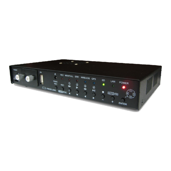
3 OVERVIEW & CONTROLS This section provides information about the front and rear panels. 3.1 Front Panel Function This switch turns the DVR ON and OFF Power Switch Image storage, capacity of 32Gb per SD card SD Card The USB 2.0 port can be used to connect to numerous USB 2.0 2..0 Port backup devices, individual external hard drives, external optical drives and USB memory sticks. -
Page 19: Rear View
3.2 Rear View Function GPS Aerial Connection (MDVR4SD-PRO Only) GPS ANT. BNC Connectors for Composite Video Signal Input Camera Input RCA Connectors for Connecting the Audio Input Audio Input 3.5 Jack Connector for Connecting the Audio & Video Output Audio & Video Out D-Sub 15-pin Connector for Connecting to a VGA Monitor VGA Output +12V Output (1.5A max) -
Page 20: Ir Remote Controller
3.3 IR REMOTE CONTROLLER Button Name Description PTZ Iris open and close (IRIS-/+) Frame by Frame (field by field) playback (ZOOM-/+) PTZ Zoom in and out SPOT / ESC Enter the spot mode / Return to the previous mode ENTER (HOME) Enter / Go home Position in PTZ mode Move the cursor left in the setup menu Move the cursor up to the next line in the setup... - Page 21 Move the cursor right in the setup menu. / Control of ) / D-ZOOM zoom in and out Auto sequence / Decrease value / AUTO / ( - ) / F(-) PTZ Focus control Freeze / Increase value / FREEZE / ( + ) / F(+) PTZ Focus control Display the search menu / SEARCH / (PRESET)
-
Page 22: Mouse Controller
3.4 MOUSE CONTROL 1. LEFT MOUSE BUTTON a) Double-click in the main window: status display. b) Double-click in the menu screen: select item or icon. 2. SCROLL WHEEL Scroll up or down to change the value of the selected item. 3. -
Page 23: Main Screen
4 MAIN SCREEN 1. REMAINING STORAGE SPACE / PLAYBACK STATUS The remaining storage space is displayed either as a percentage or in Gigabytes. If the storage overwrite is set to on, the counter will remain as 0 and the DVR will continue to write on to the SD storage from the beginning. - Page 24 6. Speed and Acceleration The driving speed of the vehicle is displayed on the screen (MDVR4SD-PRO Only). 7. Location The monitor shows the location where in you are with the DVR unit (MDVR4SD-PRO Only). Below are the icons with specific events. Front Door Rear Door Turn Right...
-
Page 25: Main Menu
5 MAIN MENU Before operating the DVR, please make sure all the cables and SD Cards are properly connected. Pressing the Menu button on the DVR or using the Remote Control, this screen pops- QUICK SETUP Quick setup enables the user to quickly setup major recording settings of the DVR. All changes made in quick setup are affected equally to all channels. -
Page 26: Image Size
5.1.2 IMAGE SIZE Select the desired IMAGE SIZE for recording as shown below by pressing the button. NTSC 720 X 480 (D1) 720 X 576 (D1) 720 X 240 (Half D1) 720 X 288 (Half D1) 360 X 240 (CIF) 360 X 288 (CIF) 5.1.3 RECORD FRAME... -
Page 27: Image Quality
5.1.4 IMAGE QUALITY Select the desired image quality using the button. There are 4 selectable image qualities: Best, Fine, Normal & Low. 5.1.5 EVENT Users can select any type of EVENT by using the button. Available events are: ALL, MOTION, V-LOSS, ALARM, GPS and OFF. -
Page 28: Pre Record Time
5.1.6 PRE RECORD TIME Select the desired time for pre-recording using the button on the remote. When video loss, alarm or motion is detected, the DVR will store pre-recorded data during the selected time. The pre-recording time can be set from 0 second to 5 seconds, and the default is “5”. -
Page 29: Audio Record
5.1.9 AUDIO RECORD Select “ON” or “OFF” using the button on the remote to record audio. 5.1.10 SAVE Press the Save icon using the Enter button in order to save the Menu Configuration. SCREEN Screen setup defines various screen related options. Any changes affect the main video. Users can select the SCREEN Menu by pressing the Enter button on the remote. -
Page 30: Auto Sequence
5.2.1 AUTO SEQUENCE In the SCREEN menu, Move the cursor to AUTO SEQUENCE ▲,▼ using the buttons. Press the ENTER button when the cursor is on AUTO SEQUENCE and the following screen appears. Move the cursor to each single or split ▲,▼... -
Page 31: Storage Free Space
5.2.2.1 STORAGE FREE SPACE In the DISPLAY menu, ▲,▼ Move the cursor using the buttons to select HDD FREE SPACE. Press the button to choose “ON” or “OFF”. * The default is “ON”. ON: Remaining capacity of the SD Memory will be displayed on the screen. 5.2.2.2 STORAGE FREE SPACE MODE In the DISPLAY menu,... -
Page 32: Record Status
5.2.2.3 RECORD STATUS In the DISPLAY menu, ▲,▼ Move the cursor using the buttons to select RECORD STATUS. Use the button to choose “ON” or “OFF”. * The default is “ON”. ON: Displays the recording status of each channel on the screen. 5.2.2.4 CLOCK DISPLAY In the DISPLAY menu,... -
Page 33: Title Display
YY/MM/DD : All dates and times will be displayed in numbers. Ex. 2009/01/01 00:00:00 MM/DD/YY : the month section will be displayed in characters. Ex. JAN. 01 2009 00:00:00 DD/MM/YY : the month section will be displayed in characters. Ex. 01. JAN 2009 00:00:00 5.2.2.6 TITLE DISPLAY In the DISPLAY menu,... -
Page 34: Border Colour
5.2.2.8 BORDER COLOUR In the DISPLAY menu, ▲,▼ Move the cursor using the buttons to select BORDER COLOUR. Use the button to choose “WHITE” or “BLACK”. The default is “WHITE”. WHITE: The colour of the border line will be displayed on the multi-channel screen in white. BLACK: The colour of the border line will be displayed on the multi-channel screen in black. -
Page 35: Speed Display Mode
5.2.2.10 SPEED DISPLAY MODE In the DISPLAY menu, ▲, ▼ Move the cursor using the buttons to select SPEED DISPLAY MODE. Use the button to choose either MILE or KILOMETRE. This will display the distance covered by the vehicle on the live screen in either Kilometres or Miles. -
Page 36: Covert
Press the ENTER button after selecting the desired channel using the ▲,▼ buttons and the following screen appears. Select the character using the ▲,▼, , buttons and then press the ENTER button. To exit this CHARACTER TABLE screen, press the ESC button. CHANNEL TITLE MODE: These are “TEXT”... -
Page 37: Camera
5.2.5 CAMERA In the SCREEN menu, Move the cursor to CAMERA using ▲,▼ buttons. Press the ENTER button when the cursor is on CAMERA and the following screen appears. You can control brightness, contrast, hue and saturation of each camera from 0% to 100%. -
Page 38: Record Program
5.3.2 RECORD PROGRAM This feature uses predefined recording modes to create new ones according to your own needs. This means you can create different programs modes using the existing predefined programs. You can have up to 10 different programs (0-9) available. These programs will be used to setup the recording schedule on the RECORD SETUP menu. -
Page 39: Audio Record
Users have to turn off recording to see the Image Quality Screen. RECORD TIME: The recording period available with the free space storage and frame rate setting. TOTAL TIME: The recording period is calculated by the total amount of IPS selected and the quality of video ** The better the image quality is, the larger the overall file size is. -
Page 40: Holiday
5.3.6 HOLIDAY In the RECORD menu, Move the cursor to “HOLIDAY” using the ▲,▼ buttons. Press the “ENTER” button to set up “HOLIDAY” and the HOLIDAY menu screen appears. Set up “ON” or “OFF” for HOLIDAY RECORD using the button. ▲,▼... -
Page 41: Event
5.4 EVENT Event setup defines various event options such as the motion grid, motion detection sensitivity, the main screen event response option, sensor input and relay output options. 5.4.1 MOTION DETECTION In the EVENT menu, Move the cursor to MOTION DETECTION ▲,▼... -
Page 42: Sensitivity
5.4.1.2 SENSITIVITY In the MOTION DETECTION menu, Move the cursor to SENSITIVITY using the ,▼ ▲ buttons. Select the sensitivity level using the button. SENSITIVITY: The higher the number is, the more sensitive the detection. 1(lowest) ~ 5(highest) 5.4.1.3 AREA SETUP In the MOTION DETECTION menu, Move the cursor to AREA SETUP using the ▲,▼... -
Page 43: Event Screen Mode
5.4.2 EVENT SCREEN MODE In the EVENT menu, Move the cursor to EVENT SCREEN MODE ,▼ using ▲ buttons. Select the EVENT SCREEN MODE using the button. SCREEN HOLD: Keep the current screen even if an event occurs. EVENT FULL: Display the full screen of the channel where the event occurs. -
Page 44: Event Indication
5.4.4 EVENT INDICATION In the EVENT menu, Move the cursor to EVENT INDICATION ,▼ using the ▲ buttons. Select “ON’ or “OFF” using the button to set the event indication. 5.4.5 SENSOR INPUT SELECT In the EVENT menu, Move cursor SENSOR INPUT ▲,▼... -
Page 45: Relay Output
5.4.6 RELAY OUTPUT In the EVENT menu, Move the cursor to “RELAY OUTPUT” using ▲,▼ buttons. Press the ENTER button when the cursor is on “RELAY OUTPUT” and the following screen appears. ▲,▼ Move the cursor using the buttons and set up the value using the button. -
Page 46: Gps
5.4.7 GPS - Only Available with the MDVR4SD-PRO Model In the EVENT menu, ▲,▼ Move the cursor to “GPS” using the buttons. Press the ENTER button when the cursor is on “GPS” and the following screen appears. Users can change the SHOCKSENSOR to either “ON”... -
Page 47: System
5.5 SYSTEM System setup defines various system settings such as storage settings, system clock, password for multiple users, video standard and language settings. Moreover the system settings can be reinitialised, saved or retrieved from the USB flash memory, as well as updating the DVR firmware. To set up the SYSTEM menu, Move the cursor to the SYSTEM icon using ▲,▼... -
Page 48: Sd Card Initialise
Note: MODE REC: Normal and Event recording. BACKUP: Only for backup. Move the Cursor to EXTERNAL SDCARD to see the following screen. Users can have the facility of connecting another SDCARD Memory Cards externally as shown above. Users can select the MODE either as BACKUP or RECORDING using button on the remote. -
Page 49: Date&Time
5.5.2.1 DATE&TIME In the CLOCK menu, Move the cursor to DATE&TIME using the ▲,▼ buttons. Press the ENTER button when the cursor is on DATE&TIME and the following screen appears. ▲,▼ Use the buttons to move the cursor to the desired position of date or time. Use the buttons to modify the current date and time. -
Page 50: Video Standard
5.5.3 VIDEO STANDARD In the SYSTEM menu, Move the cursor to VIDEO STANDARD ▲,▼ using the buttons. Users can select either “PAL”, “NTSC” or “AUTO” using the button. Press the ESC button to exit the VIDEO STANDARD menu after setting it to PAL. If you select “AUTO”, this DVR can detect NTSC/PAL signals automatically 5.5.4 LANGUAGE... -
Page 51: Password Check
5.5.5.1 PASSWORD CHECK In the ADVANCED SETUP menu, Move the cursor to PASSWORD CHECK ▲,▼ using the buttons. Select ON or OFF using the button. If OFF is selected the password menu will not work. NOTE: In cases where the PASSWORD CHECK is ON, only ADMIN and MASTER can enter the ADVANCED SETUP MENU. -
Page 52: User Authority
5.5.5.3 USER AUTHORITY In the ADVANCED SETUP menu, Move the cursor to USER AUTHORITY ▲,▼ using the buttons. Press the ENTER button when the cursor is on USER AUTHORITY and the following screen appears. Change the values using the buttons. If any functions are set to “ON”, the password is required when working with them. -
Page 53: Load Menu From File
If you want to initialize the system, move the cursor to “YES” and press the ENTER button. If not, move the cursor to “NO” and press the ▲, ENTER button. Use the buttons to move the cursor. CAUTION: MENU INITIALISE will factory default the DVR programming. PLEASE NOTE : The HDD’s data will NOT be deleted by using this function. -
Page 54: Firmware Upgrade
NOTE: It’s only possible to copy and upload the menu setting from the front USB port. 5.5.6 FIRMWARE UPGRADE In the SYSTEM menu, Move the cursor to FIRMWARE UPGRADE ▲,▼ using the buttons. Press the ENTER button when the cursor is on FIRMWARE UPGRADE and the following screen appears. - Page 55 The DVR will start reading the available upgrade file. Once the file is found, it will check the file integrity. If the file is intact the upgrade process will start. The upgrade progress will be shown as a percentage. The whole process should take approximately two minutes.
-
Page 56: Link
LINK Link setup defines various settings between the DVR and various devices, such as, the internet connection, keyboard controllers, PTZ cameras, e-mails and DVR name/location settings, in order to access and search the DVR in the CMS (Central Monitoring System). Before using the LINK menu, please make sure the LAN cable is properly connected and the required equipment is prepared. -
Page 57: Network
5.6.1 NETWORK In the LINK menu, Move the cursor to NETWORK using the ▲,▼ buttons. Press the ENTER button when the cursor is on NETWORK and the following screen appears. To exit this NETWORK menu, press the ESC button. 5.6.1.1 DHCP In the NETWORK menu, ▲,▼... -
Page 58: Subnet Mask
5.6.1.2 SUBNET MASK Inthe NETWORK menu, Move the cursor to SUBNET MASK using ,▼ the ▲ buttons. Select desired position using buttons and set the data value using the buttons. 5.6.1.3 GATEWAY In the NETWORK menu, Move the cursor to GATEWAY using the ,▼... -
Page 59: Port
5.6.1.5 PORT In the NETWORK menu, ▲,▼ Move the cursor to PORT using the buttons. Select the desired position using the buttons and set the data value using the buttons . NOTE: Port settings on the DVR and Client Viewer software must match. 5.6.1.6 DYNAMIC IP SERVER At the NETWORK menu,... -
Page 60: Backup Ip Server
5.6.1.7 BACKUP IP SERVER In the NETWORK menu, ,▼ Move the cursor to DHCP using the ▲ buttons. Select “ON” using the buttons. Move the cursor to BACKUP IP SERVER ,▼ using the ▲ buttons. Input the backup server IP address using the buttons to change the value and the ,▼... -
Page 61: Baud Rate
5.6.2.2 BAUD RATE Select the communication speed. available speeds from 1200 115200bps. The default speed is 115200. 5.6.2.3 DATA BIT Select the data bit. default bit rate is 8. 5.6.2.4 PARITY BIT Select the parity bit. Available options are ODD, EVEN and NONE. The default is NONE. -
Page 62: Stop Bit
5.6.2.5 STOP BIT Select the stop bit. Available options are 1 and 2. The default is 1. 5.6.3 The DVR can control as many Pan / Tilt / Zoom cameras which correspond to the number of channels it records on. As there are multiple vendors of PTZ cameras, the DVR also supports a variety of protocols. - Page 63 In the SCREEN menu, ▲,▼ Move the cursor to PTZ using buttons. Press the ENTER button when the cursor is on PTZ and the following screen appears. ,▼ Select the desired channel using ▲ buttons. Use the buttons to select the correct model of installed PTZ camera Select the communication speed.
-
Page 64: E-Mail
5.6.4 E-MAIL In the LINK menu, ▲,▼ Move the cursor to E-MAIL using buttons. Press the ENTER button when the cursor is on E-MAIL and the following screen appears. NOTE: If you want to use this function, you have to input the DNS address. 5.6.4.1 SEND E-MAIL In the E-MAIL menu,... -
Page 65: Smtp Server
5.6.4.2.1 SMTP SERVER Press the ENTER button to define an e-mail server. Enter the e-mail server’s address. For example: mail.domainname.com Press the ESC button to return to previous menu. 5.6.4.2.2 SMTP PORT Define port which will communicate through. Available ports are 0000 through 9999. -
Page 66: User Id And Password
5.6.4.3 DVR E-MAIL ADDRESS Press the ENTER button to define a DVR e- mail address. Move the cursor to the DVR email address using the ▲,▼ buttons . Press the ENTER button and the following screen appears. Select the characters using the ▲,▼, , buttons and press the ENTER button. -
Page 67: Dvr Name
5.6.4.5. E-MAIL ADDRESS 1 THROUGH 10 Highlight the e-mail address to send the notifications to, and then press the ENTER button to define the e-mail address. 5.6.5 DVR NAME In the E-MAIL menu, Move the cursor to DVR NAME using the ,▼... -
Page 68: Dvr Location
Select the characters using the ▲,▼, , buttons and then press the ENTER button. To exit the CHARACTER TABLE screen, press the ESC button. 5.6.6 DVR LOCATION In the E-MAIL menu, Move the cursor to DVR LOCATION using ▲,▼ buttons . Press the ENTER button and the following screen appears Select the characters using the ▲,▼,... -
Page 69: Bandwidth
5.6.7 BANDWIDTH Move the cursor to BANDWIDTH using the ▲,▼ buttons to input the network bandwidth. User can change the values from 0Mb to 10Mb using the button of the remote. To exit, press the ESC button. 5.6.8 WIRELESS Move the cursor to WIRELESS using the ▲,▼... -
Page 70: Mobile Server
5.6.8.2 MOBILE SERVER Move the cursor to the MOBILE SERVER using the ▲,▼ buttons and select the characters. Select the characters using the ▲,▼, , buttons and then press the ENTER button. To exit the CHARACTER TABLE screen, press the ESC button. 5.7 SEARCH This section outlines how to use the search facility to interrogate the unit To access the SEARCH menu move the cursor to the SEARCH icon using the ▲,▼in the MENU... - Page 71 Press the SEARCH button to access the search screen. Highlight CALENDAR SEARCH and press the ENTER button to access the CALENDAR SEARCH screen. It will start searching for the data automatically The dates that contain recorded data will be displayed in yellow, whereas dates without data will be in white.
-
Page 72: Search & Copy
5.7.2 SEARCH & COPY Move the cursor to SEARCH & COPY using ▲,▼ in the MENU screen. Press the ENTER button when the cursor is on it and the following screen appears. Search & copy allows a quick review of the recorded data and backup onto an external device and thus minimises the need to navigate through different screens to pinpoint... -
Page 73: Event Search
Time search provides an overview of the recorded data from the earliest available recording to the latest available recording. 5.7.4 EVENT SEARCH Move the cursor to EVENT SEARCH using ▲,▼ in the MENU screen. Press the ENTER button when the cursor is on it and the following screen appears. -
Page 74: Block Search
5.7.5 BLOCK SEARCH Move the cursor to BLOCK SEARCH using ,▼ the ▲ in the MENU screen. Press the ENTER button when the cursor is on it and the following screen appears. Block search has the capability to retrieve the recorded data even from hard drives that have failed during normal... -
Page 75: Bookmark Search
File search is capable of reading and playing back the data from the media used for backup. Connect the USB flash memory or the external hard disk drive into the USB port. Press the SEARCH button to access the search screen. 5.7.7 BOOKMARK SEARCH Move... -
Page 76: Log File
5.7.8 LOG FILE Move cursor BOOKMARK SEARCH icon using the ▲,▼in the MENU screen. Press the ENTER button when the cursor is on it and the following screen appears. The log file keeps a list of the important events that happened to the DVR. The log file can be saved to a USB flash memory as a text file so that it can be viewed and archived to a computer. -
Page 77: Copy Status
Move the cursor to HDD ID using the ▲,▼ buttons and select the desired HDD to copy from. HDD IDs using the buttons . Move the cursor to the desired position of COPY START TIME/ COPY END TIME using the ▲,▼, , buttons and press the button to set up the COPY START TIME and COPY END TIME. -
Page 78: Media Format
5.8.3 MEDIA FORMAT In the COPY menu, Move the cursor to MEDIA FORMAT using ▲,▼ buttons. Press the ENTER button and the following screen appears. Select formatting media using the button. Move the cursor to MEDIA FORMAT and then press the “ENTER” button. The message, “FORMATTING”... -
Page 79: Network Status
1. FIXED HDD/SD TOTAL SPACE Displays the total amount of installed storage space, including the storage space in any expansion bays. 2. FIXED HDD/SD FREE SPACE Displays the available remaining storage space, including the storage space in any expansion bays. 3. -
Page 80: Recording Bitrate
7. DYNAMIC IP SERVER Displays currently assigned backup IP server. 8. BACKUP IP SERVER Displays the IP address of the Backup Server. 9. MAC ADDRESS Displays the DVR’s MAC address (Media Access Control Address). 10. IP SERVER RESPONSE Indicates the connectivity status with the IP server. 5.9.3 RECORDING BITRATE Move the cursor to the RECORDING...
Need help?
Do you have a question about the V1.0 H.264 MDVR4SD and is the answer not in the manual?
Questions and answers