
Related Manuals for Wohler RDM-173-3G


Summary of Contents for Wohler RDM-173-3G
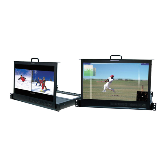
- Page 1 RDM-173-3G Rack Drawer Dual Input, LCD, Audio/ Video Monitor User Guide Part Number 821099, Revision A...
- Page 2 © 2013 Wohler Technologies, Inc. All rights reserved. This publication is protected by federal copyright law. No part of this publication may be copied or distributed, stored in a retrieval system, or translated into any human or computer language in any form or by any means electronic, mechanical, manual, magnetic, or otherwise, or disclosed to third parties without the express written permission of Wohler Technologies.
-
Page 3: Table Of Contents
RDM-173-3G Introduction Overview The RDM-173-3G dual input, LCD video monitors are high- performance, professional LCD monitors that support advanced 10-bit digital processing technology with 3D comb filter and de-interlace, accurate scaling engine, GAMMA correction and color temperature adjustments to achieve the best possible image display. -
Page 4: Safety
RD M - 1 7 3- 3G Sa f e t y Safety Important Safety Instructions Read, keep, and follow all of these instructions; heed all warnings. Do not use this equipment near water, rain or moisture. Use only a dry cloth to clean the equipment. Do not install near any heat source such as a radiator, heat register, amplifier, or stove. -
Page 5: Installation Recommendations
RDM-173-3G I n s t a l la t io n R e c om m e n d a t io n s Safety Symbols WARNING: The symbol to the left warns of electric shock hazard inside the unit. -
Page 6: Unpacking And Installation
RD M - 1 7 3- 3G U n p a ck in g a n d I n s t a ll a t io n Note: HDMI 1.3 or 1.4 cable lengths of 2m (6 feet) are guaranteed to work well. - Page 7 • Warranty card Mounting The RDM-173-3G monitor comes standard with a rack mounted drawer. It is to be installed using the following steps: Withdraw the monitor from its drawer cage by unscrewing the front panel captive fasteners and pulling the handle out toward you.
- Page 8 RD M - 1 7 3- 3G U n p a ck in g a n d I n s t a ll a t io n Figure 1–2 Set Monitor Assembly Aside The cage for the drawer must be attached at both the front and back of the rack.
- Page 9 RDM-173-3G U n p a c k in g a nd I n s t a ll a t io n IMPORTANT: Very deep racks require wire or strap hangers secured to rack walls to support the weight at the rear.
- Page 10 U n p a ck in g a n d I n s t a ll a t io n shows the RDM-173-3G tilted up into viewing position, although it is shown outside of the rack enclosure for clarity. You can see the connectors in this figure.
-
Page 11: Features
RDM-173-3G F ea t u r e s Features The RDM-173-3G monitor provides the following features: • 178° viewing angle • Multi-format analog and digital audio signals • Adjustment of the parameters for each channel • High-quality waveform or vector monitoring (as SUB input) •... -
Page 12: Front Panel Features
F r o nt P a n el F e a t u r e s Front Panel Features The following feature descriptions refer to Figure 1–6 below. Figure 1–6 RDM-173-3G Front Panel (PIP) Status - Sub LED Tally Status - Main Buttons PIP display... - Page 13 RDM-173-3G F r o n t P a n el F ea t u r e s , and define the static operation. DISPLAY IMD COLOR IMD CHAR The IMD menu defines the dynamic tally operations. • Timecode: The display format for the timecode is HH: MM: SS: FF.
- Page 14 Display Menu on page 22 Config Menu on page Figure 1–7 RDM-173-3G Waveform Display (PBP) Main Input (in PBP Waveform or Vector display mode) as SUB Input (in PBP display mode)
-
Page 15: Rear Panel Features
R e a r P a n el F ea t u r e s Rear Panel Features Figure 1–8 RDM-173-3G Complete Rear Panel 82 10 99 : RD M -1 73 -3 G U se r G u id e... - Page 16 RD M - 1 7 3- 3G Re a r Pa n e l F e a t u r es Figure 1–9 RDM-173-3G Rear Panel - Lower Right • (jack): Accepts power plug from the included 12 VDC DC IN power adapter.
- Page 17 RS485 Port Figure 1–11 on page 16 Table 1–2 on page 16 for connection details. Figure 1–10 RDM-173-3G Rear Panel - Upper Left • (2 BNC) and (BNC): These inputs SDI Video Inputs SDI Output and output receive 3G/HD/SD-SDI signals. The output produces a...
- Page 18 RD M - 1 7 3- 3G Re a r Pa n e l F e a t u r es • (BNC) (BNC) (BNC), analog Line 2 Inputs: CVBS/Y , Pb/C , Pr composite, S-video, and component video. Table 1–1 GPI Pin Out Function GPI 1...
-
Page 19: Using The Menu System
U s i ng t h e M e n u S y s t e m Using the Menu System Configuring the RDM-173-3G monitor is accomplished in the Menu . Each of the menus is explained on this and the following System pages. -
Page 20: Status Menu
RD M - 1 7 3- 3G U s in g t h e M en u S y s t e m Status Menu Note that none of the options displayed on the menu are STATUS editable. Table 1–3 Status Menu Default Parameters... - Page 21 RDM-173-3G U s i ng t h e M e n u S y s t e m Marker Menu Important: MARKER is disabled when SCAN mode is NATIVE, or when the input signal is DVI or VGA. Table 1–5...
-
Page 22: Audio Menu
RD M - 1 7 3- 3G U s in g t h e M en u S y s t e m Table 1–5 Marker Menu (Continued) Default Parameters Domain Range Value Sets the luminance (white level or brightness) to display safety, center, and area marker line, where: MARKER LEVEL •... - Page 23 RDM-173-3G U s i ng t h e M e n u S y s t e m Table 1–6 Audio Menu (Continued) Default Parameters Domain Range Value Select embedded audio for the right speaker/headphone/line output: SPEAK OUT R EBD CH1 •...
-
Page 24: Display Menu
RD M - 1 7 3- 3G U s in g t h e M en u S y s t e m Table 1–6 Audio Menu (Continued) Default Parameters Domain Range Value TOP (HORIZ) BOT (HORIZ) TOP LEFT (VERT) METER POSITION BOT LEFT BOT LEFT (VERT) BOT RIGHT (VERT) - Page 25 RDM-173-3G U s i ng t h e M e n u S y s t e m Table 1–7 Display Menu (Continued) Default Parameters Domain Range Value WAVE UNDER LIMIT • VITC • TIMECODE • D-VITC • Closed Caption Menu Table 1–8...
- Page 26 RD M - 1 7 3- 3G U s in g t h e M en u S y s t e m Table 1–9 Config Menu (Continued) Default Parameters Domain Range Value • SMALL/LARGE PIP SIZE SMALL • TOP RIGHT •...
- Page 27 RDM-173-3G U s i ng t h e M e n u S y s t e m Table 1–10 Color Temp Menu (Continued) Default Parameters Domain Range Value RED BIAS Presets Factory GREEN BIAS Calibrated BLUE BIAS When is selected,...
- Page 28 RD M - 1 7 3- 3G U s in g t h e M en u S y s t e m Function Key Menu This menu lets you customize what you need each function key to do. Table 1–11 Function Key Menu Default Parameters...
- Page 29 RDM-173-3G U s i ng t h e M e n u S y s t e m GPI Menu Table 1–12 GPI Menu Default Parameters Domain Range Value Select the function that each GPI will control. TALLY GPI 1 GREEN •...
- Page 30 RD M - 1 7 3- 3G U s in g t h e M en u S y s t e m IMD Menu Table 1–13 IMD Menu Default Parameters Domain Range Value = Displays IMD DISPLAY = Does not display Select the color in which to display the IMD text: •...
- Page 31 RDM-173-3G U s i ng t h e M e n u S y s t e m Table 1–13 IMD Menu Default Parameters Domain Range Value Select the communications baud rate: • 2400 • 4800 • 9600 9600 BAUD RATE •...
-
Page 32: Specifications
• = Inhibits all keys except KEY INHIBIT (to make POWER MENU setup changes) Specifications The general specifications of the RDM-173-3G monitor is listed in Table 1–15 below. Table 1–15 RDM-173-3G Specifications Specification RDM-173-3G 11” H (7RU) x 16.3” W x 1.5” D... - Page 33 Audio Inputs 4 RCAs: Analog stereo for EXT sources Audio Outputs 3.5mm TRS: Headphone Table 1–17 below distinguishes each of the HDM models. Table 1–17 RDM-173-3G Distinctions Among Each Model Category Specification 3G-A SDI 1080p: (60/59.94/50) SMPTE 424M 1080p: (23.98, 24, 25, 29.97, 30)
- Page 34 RD M - 1 7 3- 3G Sp e ci fi ca t io n s Table 1–18 RDM-173-3G CVBS I/O Specifications Specification HDM Values Differential Gain < 1% Differential Phase < 1.5° Table 1–19 below lists the specifications for SDI inputs.
-
Page 35: Technical Function Overview
RDM-173- 3G monitor. Figure 1–12 RDM-173-3G Block Diagram 82 10 99 : RD M -1 73 -3 G U se r G u id e © 20 13 Wo hl e r Te c hn ol og i e s , In c . A l l r ig h ts re se rv ed .
Need help?
Do you have a question about the RDM-173-3G and is the answer not in the manual?
Questions and answers