Table of Contents
Advertisement
Quick Links
Advertisement
Table of Contents

Related Manuals for Technisonic Industries Limited TFM-556


Summary of Contents for Technisonic Industries Limited TFM-556
- Page 1 VHF High/VHF Low/UHF MULTI-BAND FM AIRBORNE TRANSCEIVER MODEL TFM-556 Installation and Operating Instructions Til Document No. 03RE328 Rev. n/c September 2003 Technisonic Industries Limited 240 Traders Boulevard, Mississauga, Ontario L4Z 1W7 Tel:(905)890-2113 Fax:(905)890-5338 www.til.ca...
- Page 2 RSS 141 as amended. The equipment is not permitted to be installed in a fixed or mobile, land based station in Canada. WARRANTY INFORMATION The Model TFM-556, Transceiver is under warranty for one year from date of purchase. Failed units caused by defective parts, or workmanship should be returned to: Technisonic Industries Limited...
- Page 3 Summary of DO-160C Environmental Testing for Technisonic Model TFM-556, Low-band VHF, High- band VHF and UHF Transceiver: Conditions Section Description of Conducted Tests Temperature and Altitude Equipment tested to categories B2 and Vibration Equipment is tested without shock mounts to categories B, M and N.
-
Page 4: Table Of Contents
TABLE OF CONTENTS Paragraph Title Page SECTION 1 GENERAL DESCRIPTION Introduction ..........1-1 Description . - Page 5 LIST OF TABLES Table No. Title Page 9-pin D and 15-Pin D Connections ....... . 3-3 LIST OF ILLUSTRATIONS Figure No.
-
Page 6: General Description
138-150 MHz portion of the VHF band. If the TFM-556 transceiver is used in CANADA, VHF operation is restricted to the following sub bands: 138-144, 148-148.99, 149.005-150.005 and 150.05- 174 MHz. - Page 7 TECHNICAL CHARACTERISTICS Specification Characteristic GENERAL Model Designation: TFM-556 Frequency Range: 66 to 88, 138 to 174 and 403 to 512 MHz Tuning Increments: 2.5 kHz Operating Mode: F3E simplex or semi-duplex Channel Spacing: 25 or 12.5 kHz Physical Dimensions (including heatsink): Approx.
- Page 8 TECHNICAL CHARACTERISTICS (continued) VHF RECEIVER Sensitivity at 12 dB SINAD Better than 0.35 µV Adjacent Channel Selectivity -75 dB (25 kHz) -70 dB (12.5 kHz) Spurious Attenuation -90 dB Third Order Intermodulation -70 dB Image Attenuation -80 dB FM Acceptance ±...
- Page 9 VHF, VHF LOW and UHF TRANSMITTER RF Power Output 1 watt or 10 watts Output Impedance 50 ohms Maximum Deviation ±5 kHz (25 kHz mode) (In narrowband mode) ±2.5 kHz(12.5kHz mode) Spurious Attenuation -90 dB below carrier level Frequency Stability ±...
-
Page 10: Operating Instructions
SECTION 2 OPERATING INSTRUCTIONS FEATURES The equipment has several important operating features which provide maximum flexibility, performance and versatility. These features include: The UHF band can be configured to be operated independently of the VHF High and VHF Low bands or all three bands can operate as a single unit. The unit can be set up as a cross band repeater, linking a VHF High and UHF frequency in both directions. - Page 11 f) REMOTE BS - Only used when an RC-550 slave control head is attached. Setting this feature on will give the transmit selection to the Band Select switch on the RC-550 rather than on the radio. This is useful when the operator at the RC-550 is using the VHF high and low bands.
-
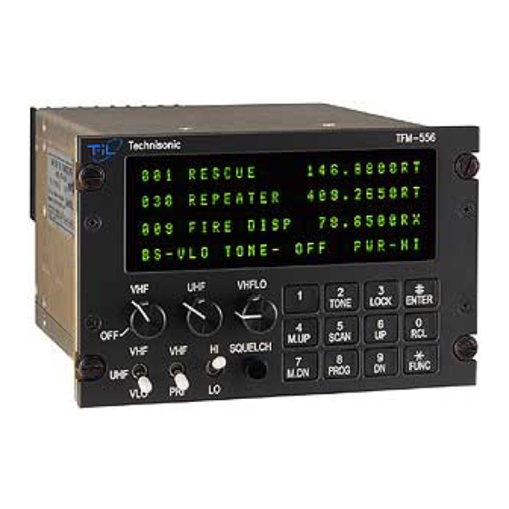
Page 12: Operating Instructions
OPERATING INSTRUCTIONS (See Figure 2-1) Switch power on by turning the VHF volume clockwise. Depending how the radio is configured, either the last programmed or last displayed frequencies will appear on the screen. The transceiver is now in normal operating mode. NOTE: VHF high band will be referred to as “VHF”... - Page 13 PRIORITY SCANNING, SELECTIVE MEMORY CHANNEL SCANNING AND SCAN LISTS Instead of breaking up the 200 channels into blocks for scanning, the TFM-556 has 5 scan lists per band (VHF high and UHF only). Any of the 200 channels can be assigned to any one or more of these 5 scan lists.
-
Page 14: Scanning Function
SCANNING FUNCTION (5 second talkback delay) Select the band you wish to scan with the band switch. (You can not scan VHF Low band). To start scanning of the memory channels, press FUNC then SCAN and then the number (1,2,3,4,5) of the desired scan list. -
Page 15: Variable Frequency Mode Function
VARIABLE FREQUENCY MODE FUNCTION To enter variable frequency mode, press RCL, 0,0,0, then ENTER or enter a frequency in the direct entry mode described above. The memory channel that you were just in will still be valid but now you can manually adjust the frequency with the M.UP, M.DN, UP and DN keys. - Page 16 Number Tone Number Tone Number Tone 67.0 162.2 177.3* 71.9 167.9 183.5* 74.4 173.8 189.9* 77.0 179.9 196.6* 79.7 186.2 199.5* 82.5 192.8 206.5* 85.4 203.5 210.7* 88.5 33.0* 218.1* 91.5 35.4* 225.7* 94.8 36.6* 229.1* 97.4 37.9* 233.6* 100.0 39.6* 241.8* 103.5...
-
Page 17: Cross Band Repeat
2.14 CROSS BAND REPEAT The TFM-556 can act as a cross band repeater between VHF (high band only) and UHF. To enter repeat mode, press FUNC and then 9. The status line will show REPEAT instead of the band switch selection. - Page 18 Note: If your serial port is a 9 pin connector, instead of the 25 pin use a female 9 pin D connector, connecting: Yellow - pin 3 Blue pin 2 Black pin 5 FIGURE 2-2 TFM-556 Transceiver PC Up/Download Cable - wiring diagram...
-
Page 19: Installation Instructions
TRANSCEIVER INSTALLATION The TFM-556 transceiver is designed to be Dzus mounted and should be installed in conjunction with an IN-550 installation kit. See Figure 3-1 for an outline drawing of the unit with dimensions to facilitate the installation. - Page 20 FIGURE 3-1 Outline Drawing for Model TFM-556 Transceiver...
- Page 21 INSTALLATION - PIN LOCATIONS AND CONNECTIONS (continued) 15 Pin D Connections - Use FEMALE Connector Pin # Description 600 Ohm Output 1 Data Output Panel Lighting (28VDC or 5VAC) Memory Up Memory Down Mic Signal Input 1 Main Power +28VDC Main Ground 4 ohm Speaker Output 4 ohm/600 ohm Output Ground...
- Page 22 FIGURE 3-2 Wiring connections for the TFM-556 Transceiver...
-
Page 23: Wiring Instructions
Figure 3-2 shows all required connections and recommended wire sizes for the TFM-556 Transceiver. If problems with the correct operation of the UHF/FM Transmit function of a TFM-556 are encountered on a specific airframe, a DC power line filter may be required. Typical problems encountered are that UHF/FM will not transmit on high power or will not open a repeater when using a CTCSS transmit tone. -
Page 24: Data Input
Data communications equipment requiring direct access to the modulator and discriminator an be connected via pins 2 and 11. Data cannot be transmitted in CANADA unless equipment is approved for use with the TFM-556 by the communications regulatory authority. INTERNAL PROGRAMMING ENABLE/DISABLE JUMPER The programming and direct frequency entry modes can be disabled by removing the internal enable/disable jumper strap from pins 1 and 2 of J10. -
Page 25: Transmitter Power Adjustments
TRANSMITTER POWER ADJUSTMENTS The transmitter power is adjusted to a maximum of 10 watts in high power mode and 1 watt in low power mode over the transceiver operating bandwidth at the factory. If transmitter RF power re-adjustment is required, perform as follows: Select the band that you wish to adjust on the band select switch. - Page 26 FIGURE 3-4 External Adjustment Access Holes...
-
Page 27: Squelch Adjustment
3.11 SQUELCH ADJUSTMENT The squelch on all receivers is factory set to open at approximately 22 dB SINAD. This adjustment can be made or altered to suit local conditions as follows: Set the receiver to 157.000 MHz for VHF, 457.000 MHz for UHF or 41 MHz for VHF Low band.. - Page 28 Adjust the wide band deviation limit potentiometer, R30 on the UHF Rx/Tx module (see Figure 3-6) to produce a ±4.20 kHz deviation. Select narrow band mode on the UHF band and adjust the narrowband deviation limit potentiometer, R76 on the UHF Rx/Tx module to produce a ±2.10 kHz deviation.
- Page 29 UHF Receiver/Transmitter PCB Module Notes: R11 is for 25 kHz (wide band) Deviation Adjustment R102 is for 12.5 kHz (narrowband) Deviation Adjustment FIGURE 3-6 UHF Deviation Adjustment Potentiometer Location 3-10...
- Page 30 VHF LOW Band Receiver/Transmitter PCB Module Notes: R21 is for 25 kHz (wide band) Deviation Adjustment R16 is for 12.5 kHz (narrowband) Deviation Adjustment FIGURE 3-7 VHF LOW Deviation Adjustment Potentiometer Location 3-11...
- Page 31 3.12 TRANSMITTER DEVIATION ADJUSTMENT - continued VHF LOW: Remove the top cover of the transceiver. Set the VLO operating frequency to 77.000 MHz and connect an appropriate test receiver to the RF output connector. Ensure that the output of the transceiver is terminated into a proper dummy load.
-
Page 32: Post Installation Emi Test
POST INSTALLATION EMI TEST PURPOSE The purpose of this test is to identify any interference that the TFM-556 may cause with existing aircraft systems. As the TFM-556 installation may include the ATC-550 antenna tuner controller, this test, as required, will also identify any interference caused by the ATC-550. - Page 33 For example it is permissible for a VFR certified GPS to lose navigation capability while the TFM-556 unit is transmitting, providing that it recovers properly and promptly, but it is not permissible for an IFR Approach certified GPS to be affected in the same way.
- Page 34 Determine if the image frequency for the VHF Comm falls within the range of the TFM-556. If so, select a set of frequencies that will cause the TFM-556 to be set as close as possible to the image frequency. Any one of the many possible sets will suffice. Record those values in the spaces provided in the following chart.
- Page 35 Determine if the image frequency for the VOR/ILS Nav falls within the range of the TFM-556. If so, select two sets of frequencies that will cause the TFM-556 to be set as close as possible to the image frequency. Choose one set in the localizer frequency range and one in the VOR frequency range.
- Page 36 Modulate the TFM-556 transmitter on the following frequencies for at least 20 seconds. Observe the Glideslope displays. Look for any movement of flags or needles on the navigation display. FREQUENCIES RESULTS G/S #1 TFM-556 PASS FAIL 334.7 (108.1) 66.9400 334.7 (108.1) 83.6750...
- Page 37 Operate the TFM-556 transmitter on the following frequency for at least 20 seconds. Observe the Transponder for any spurious replies or loss of reply to test set. FREQUENCIES TRANSPONDER #1 TRANSPONDER #2 TFM-556 PASS FAIL PASS FAIL 85.0000 MHz 85.8350 MHz 171.6650 MHz...
- Page 38 Modulate the TFM-556 transmitter on the following frequencies for at least 20 seconds. Observe the DME displays. Look for loss of distance information on the display. FREQUENCIES RESULTS DME 1 TFM-556 PASS FAIL 978 (108.0) 81.5000 978 (108.0) 163.0000 978 (108.0) 489.0000...
- Page 39 While turning the ATC-550 on and off as often as required, listen for any noise or detected audio signals on the HF receiver audio FREQUENCIES RESULTS HF #1 PASS FAIL 16 MHz FREQUENCIES RESULTS HF #2 PASS FAIL 16 MHz NOTES:...
- Page 40 NOTE: For the following tests, select a frequency at the top, middle and bottom of each band of the TFM-556 transceiver. 66 to 88 MHz 138 to 174 MHz 403 to 512 MHz Band Band Band Frequency #1 Frequency #2 Frequency #3 At a safe altitude engage the autopilot or stability augmentation system.
- Page 41 List the power plant, fuel and other electric instruments in the chart provided and note any anomalies that occur while transmitting or switching ATC-550 antenna tuner controller on and off. Assess the results. STEP SYSTEM PASS FAIL NOTES Com 1&2 (High Band) Transponder &...
- Page 42 STEP SYSTEM PASS FAIL NOTES Directional Gyro Fuel Pressure Oil Temp Amps Bus Voltage Fuel % A-11...
- Page 43 STEP SYSTEM PASS FAIL NOTES Torque % Annunciators Digital Clock Oil Pressure DME 1&2 (Low Band and Mid Band) A-12...
- Page 44 STEP SYSTEM PASS FAIL NOTES NOTES: A-13...
Need help?
Do you have a question about the TFM-556 and is the answer not in the manual?
Questions and answers