Table of Contents
Advertisement
Quick Links
Models:
SL-550METRO
SL-550METRO-LP
• Important operating
a n d m a i n t e n a n c e
instructions included.
WARNING: If the information in these
instructions is not followed exactly, a fi re
or explosion may result causing property
damage, personal injury, or death.
• DO NOT store or use gasoline or other fl am-
mable vapors and liquids in the vicinity of this
or any other appliance.
• What to do if you smell gas
- DO NOT try to light any appliance.
- DO NOT touch any electrical switch. DO
NOT use any phone in your building.
- Immediately call your gas supplier from a
neighbor's phone. Follow the gas suppli-
er's instructions.
- If you cannot reach your gas supplier, call
the fi re department.
• Installation and service must be performed
by a qualifi ed installer, service agency, or the
gas supplier.
This appliance may be installed as an OEM installation in
manufactured home (USA only) or mobile home and must be
installed in accordance with the manufacturer's instructions
and the manufactured home construction and safety standard,
Title 24 CFR, Part 3280 or Standard for Installation in Mobile
Homes, CAN/CSA Z240MH, in Canada.
This appliance is only for use with the type(s) of gas indicated
on the rating plate.
NOTICE
DO NOT DISCARD THIS MANUAL
• Read, understand and follow
these instructions for safe
installation and operation.
Heat & Glo • SL-550METRO, SL-550METRO-LP • 2185-900 Rev. D • 8/09
Owner's Manual
Installation and Operation
• Leave this manual with
party responsible for use
and operation.
WARNING
HOT SURFACES!
Glass and other surfaces are hot during
operation AND cool down.
Hot glass will cause burns.
• DO NOT touch glass until it is cooled
• NEVER allow children to touch glass
• Keep children away
• CAREFULLY SUPERVISE children in same room as
fi replace.
• Alert children and adults to hazards of high temperatures.
High temperatures may ignite clothing or other fl ammable
materials.
• Keep clothing, furniture, draperies and other fl ammable
materials away.
This appliance has been supplied with an integral barrier
to prevent direct contact with the fi xed glass panel. DO
NOT operate the appliance with the barrier removed.
Contact your dealer or Hearth & Home Technologies if the
barrier is not present or help is needed to properly install one.
In the Commonwealth of Massachusetts installation must be
performed by a licensed plumber or gas fi tter.
See Table of Contents for location of additional Commonwealth
of Massachusetts requirements.
Installation and service of this appliance should be
performed by qualifi ed personnel. Hearth & Home
Technologies suggests NFI certifi ed or factory trained
professionals, or technicians supervised by an NFI
certifi ed professional.
1
Advertisement
Table of Contents

Related Manuals for Heat & Glo SL-550METRO-LP


Summary of Contents for Heat & Glo SL-550METRO-LP
- Page 1 Technologies suggests NFI certifi ed or factory trained This appliance is only for use with the type(s) of gas indicated professionals, or technicians supervised by an NFI on the rating plate. certifi ed professional. Heat & Glo • SL-550METRO, SL-550METRO-LP • 2185-900 Rev. D • 8/09...
-
Page 2: Congratulations
00,000 00,000 00,000 00,000 MIN. MIN. INPUT INPUT BTUH: BTUH: 00,000 00,000 00,000 00,000 Serial Serial ORIFICE ORIFICE SIZE: SIZE: #XXXXX #XXXXX #XXXXX #XXXXX XXXXXXXX XXXXXXXX (Serie): (Serie): Heat & Glo • SL-550METRO, SL-550METRO-LP • 2185-900 Rev. D • 8/09... -
Page 3: Table Of Contents
E. Junction Box Installation......54 A. Vent Termination Minimum Clearances ....21 Heat & Glo • SL-550METRO, SL-550METRO-LP • 2185-900 Rev. D • 8/09... - Page 4 D. Contact Information ......77 = Contains updated information. Heat & Glo • SL-550METRO, SL-550METRO-LP • 2185-900 Rev. D • 8/09...
-
Page 5: Limited Lifetime Warranty
B. Limited Lifetime Warranty Heat & Glo • SL-550METRO, SL-550METRO-LP • 2185-900 Rev. D • 8/09... - Page 6 B. Limited Lifetime Warranty (continued) Heat & Glo • SL-550METRO, SL-550METRO-LP • 2185-900 Rev. D • 8/09...
-
Page 7: Listing And Code Approvals
• A 110-120 VAC circuit for this product must be protected with ground-fault circuit-interrupter protection, in compliance with the applicable electrical codes, when it is installed in locations such as in bathrooms or near sinks. Heat & Glo • SL-550METRO, SL-550METRO-LP • 2185-900 Rev. D • 8/09... -
Page 8: Requirements For The Commonwealth Of Massachusetts
VENT DIRECTLY BELOW. KEEP CLEAR OF ALL OB- of the installation. STRUCTIONS”. See Gas Connection section for additional Common- wealth of Massachusetts requirements. Heat & Glo • SL-550METRO, SL-550METRO-LP • 2185-900 Rev. D • 8/09... -
Page 9: User Guide
• Install a switch lock or a wall/remote control with child protection lockout feature. DECORATIVE DOORS (NOT SHOWN) SECTION 2.D. FIXED GLASS ASSEMBLY (NOT SHOWN) SECTION 14.F. MANTEL HEARTH CLEAR SPACE SECTION 2.C. Figure 2.1 General Operating Parts Heat & Glo • SL-550METRO, SL-550METRO-LP • 2185-900 Rev. D • 8/09... -
Page 10: Clear Space
Contact your dealer or Hearth & Home Technologies if the barrier is not present or help is needed to properly install one. For more information refer to the instructions supplied with your decorative door or front. Heat & Glo • SL-550METRO, SL-550METRO-LP • 2185-900 Rev. D • 8/09... -
Page 11: Lighting Instructions (Ipi)
For additional information on operating your Hearth & Home Technologies fi replace, please refer to www.fi replaces.com. Final inspection by Heat & Glo • SL-550METRO, SL-550METRO-LP • 2185-900 Rev. D • 8/09... -
Page 12: After Fireplace Is Lit
In an IntelliFire ignition system, the pilot fl ame should turn off when appliance is turned off. continually? Some optional control systems available with IPI models may allow pilot fl ame to remain lit. Heat & Glo • SL-550METRO, SL-550METRO-LP • 2185-900 Rev. D • 8/09... -
Page 13: Maintenance And Service
• Carefully set fi xed glass assembly in place on fi replace. Hold glass in place with one hand and secure glass latches with the other hand. • Reinstall door or decorative front. Heat & Glo • SL-550METRO, SL-550METRO-LP • 2185-900 Rev. D • 8/09... -
Page 14: Maintenance Tasks-Qualifi Ed Service Technician
• Verify that there is not a short in fl ame sense circuit by checking continuity between pilot hood and fl ame sensing rod. Replace pilot as necessary. Heat & Glo • SL-550METRO, SL-550METRO-LP • 2185-900 Rev. D • 8/09... - Page 15 (Either cobrahead or SIT) Figure 3.1 IPI Pilot Flame Patterns Heat & Glo • SL-550METRO, SL-550METRO-LP • 2185-900 Rev. D • 8/09...
-
Page 16: Getting Started
FRAMING HEADED OFF IN CEILING JOISTS (SECTION 8.C) OPTIONAL WALL SWITCH MANTEL AND MANTEL LEG (SECTION 5.D) SURROUND HEARTH EXTENSION GAS LINE (SECTION 11) Figure 4.1 Typical System Heat & Glo • SL-550METRO, SL-550METRO-LP • 2185-900 Rev. D • 8/09... -
Page 17: Design And Installation Considerations
Plumb line Safety glasses Level Reciprocating saw Manometer Flat blade screwdriver Non-corrosive leak check solution 1/2 - 3/4 in. length, #6 or #8 Self-drilling screws Heat & Glo • SL-550METRO, SL-550METRO-LP • 2185-900 Rev. D • 8/09... -
Page 18: Framing And Clearances
Models Min. Min. 59-1/2 62-1/4 16-1/4 48-1/2 68-3/4 15-1/16 7-1/2 7-1/8 See Section SL-550METRO 5.D for Alcove Installation 1067 1511 1118 1581 1232 1746 Figure 5.1 Appliance Locations Heat & Glo • SL-550METRO, SL-550METRO-LP • 2185-900 Rev. D • 8/09... -
Page 19: Constructing The Appliance Chase
SL-550METRO 1092 * Adjust framing dimensions for interior sheathing (such as sheetrock) **Adjust framing dimension for clean fi nishing technique. See Section 13.D. Figure 5.2 Clearances to Combustibles Heat & Glo • SL-550METRO, SL-550METRO-LP • 2185-900 Rev. D • 8/09... -
Page 20: Mantel And Wall Projections
See Figure 5.7. 11-1/2 IN.. 1/2 IN. 1 IN. 1 IN. = NON-COMBUSTIBLE ZONE Figure 5.4 Non-Combustible Zone Figure 5.7. Combustible Tape Area Heat & Glo • SL-550METRO, SL-550METRO-LP • 2185-900 Rev. D • 8/09... -
Page 21: Termination Locations
Over 16/12 to 18/12 ..........7.0 Over 18/12 to 20/12 ..........7.5 Over 20/12 to 21/12 ..........8.0 * 3 foot minimum in snow regions Figure 6.1 Minimum Height From Roof To Lowest Discharge Opening Heat & Glo • SL-550METRO, SL-550METRO-LP • 2185-900 Rev. D • 8/09... - Page 22 Figure 6.3 Minimum Clearances for Termination CAUTION: IF EXTERIOR WALLS ARE FINISHED WITH VINYL SIDING, IT IS SUGGESTED THAT A VINYL PROTECTOR KIT BE INSTALLED. Heat & Glo • SL-550METRO, SL-550METRO-LP • 2185-900 Rev. D • 8/09...
-
Page 23: Vent Information And Diagrams
76 to 152 DVP12A 3 to 12 76 to 305 DVP12MI 3 to 12 76 to 305 DVP24MI 3 to 24 76 to 610 Figure 7.2 DVP Pipe Effective Length Heat & Glo • SL-550METRO, SL-550METRO-LP • 2185-900 Rev. D • 8/09... -
Page 24: Use Of Flex Vent
However, the vent at- 1 in. tachment point and the fi restop loca- CLEARANCE tion are considered to be supports. Figure 7.3 Heat & Glo • SL-550METRO, SL-550METRO-LP • 2185-900 Rev. D • 8/09... -
Page 25: Vent Diagrams
V + H MAX. = 40 ft. (12.2 m) WARNING Fire Risk. • A one foot minimum vertical vent section is required before installing fi rst elbow. Figure 7.4 Heat & Glo • SL-550METRO, SL-550METRO-LP • 2185-900 Rev. D • 8/09... - Page 26 MAX. = 40 ft. (12.2 m) WARNING Fire Risk. • A one foot minimum vertical vent section is required before installing fi rst elbow. INSTALLED HORIZONTALLY Figure 7.5 Heat & Glo • SL-550METRO, SL-550METRO-LP • 2185-900 Rev. D • 8/09...
- Page 27 + H cannot exceed 40 ft. (12.2 m) WARNING Fire Risk. • A one foot minimum vertical vent section is required before installing fi rst elbow. Figure 7.6 Heat & Glo • SL-550METRO, SL-550METRO-LP • 2185-900 Rev. D • 8/09...
- Page 28 fl ame height. If the vent confi guration has a total vertical of 15-60 feet, an exhaust restrictor may be need- ed. The exhaust restrictor can be located in the appliance manual bag. Heat & Glo • SL-550METRO, SL-550METRO-LP • 2185-900 Rev. D • 8/09...
- Page 29 (see Figure 7.3). WARNING Fire Risk. • A one foot minimum vertical vent section is required before installing fi rst elbow. Figure 7.9 Heat & Glo • SL-550METRO, SL-550METRO-LP • 2185-900 Rev. D • 8/09...
- Page 30 (see Figure 7.3). WARNING Fire Risk. • A one foot minimum vertical vent section is required before installing fi rst elbow. INSTALLED HORIZONTALLY Figure 7.10 Heat & Glo • SL-550METRO, SL-550METRO-LP • 2185-900 Rev. D • 8/09...
- Page 31 Note: There MUST be a 25% reduction in total H when using fl ex vent except when using the simple up and out installation (see Figure 7.3). Figure 7.11 Heat & Glo • SL-550METRO, SL-550METRO-LP • 2185-900 Rev. D • 8/09...
- Page 32 Figure 7.12 Rear Vent - Horizontal Termination = 9 in. (229 mm) Maximum One 45º Elbow Note: Use DVP Series components only. Figure 7.13 Heat & Glo • SL-550METRO, SL-550METRO-LP • 2185-900 Rev. D • 8/09...
-
Page 33: Rear Vent - Horizontal Termination
6 ft. 1.8 m 13-1/2 ft. 4.1 m MAX. = 7-1/2 ft. (2.3 m) MAX. = 13-1/2 ft. (4.1 m) MAX. = 40 ft. (12.2 m) Figure 7.15 Heat & Glo • SL-550METRO, SL-550METRO-LP • 2185-900 Rev. D • 8/09... - Page 34 6-1/2 ft. 2.0 m 3 ft. 914 mm H MAX. = 6-1/2 ft. (2 m) V + H+ H MAX. = 40 ft. (12.2 m) INSTALLED HORIZONTALLY Figure 7.17 Heat & Glo • SL-550METRO, SL-550METRO-LP • 2185-900 Rev. D • 8/09...
- Page 35 4.4 m MAX. = 7-1/2 ft. (2.3 m) MAX. = 14-1/2 ft. (4.4 m) MAX. = 40 ft. (12.2 m) Note: Use DVP Series components only. Figure 7.18 Heat & Glo • SL-550METRO, SL-550METRO-LP • 2185-900 Rev. D • 8/09...
-
Page 36: Coaxial To Colinear Venting
CAUTION! DO NOT use any fl ue restrictor when vent- ing with the DV-46DVA-GCL adapter and LINK-DV30B kit. This may result in poor fl ame appearance, sooting, pilot malfunction, or overheating. Heat & Glo • SL-550METRO, SL-550METRO-LP • 2185-900 Rev. D • 8/09... -
Page 37: Rear Vent
10 ft. 3.05 m 0 ft. 0 mm Minimum 10 ft. 3.05 m Maximum 40 ft. 12.2 m 2 ft. 610 mm Maximum 40 ft. 12.2 m Figure 7.21 Heat & Glo • SL-550METRO, SL-550METRO-LP • 2185-900 Rev. D • 8/09... -
Page 38: Vent Clearances And Framing
* Shows center of vent framing hole for top or rear venting. The center of the hole is one (1) inch (25.4 mm) above the center of the horizontal vent pipe. Figure 8.2 Wall Penetration Heat & Glo • SL-550METRO, SL-550METRO-LP • 2185-900 Rev. D • 8/09... -
Page 39: Install The Ceiling Firestop
INSTALL ATTIC INSULATION SHIELDS BEFORE OR AFTER INSTALLATION OF VENT SYSTEM 3 FASTENERS PER SIDE CEILING FIRESTOP CEILING FIRESTOP INSTALLED BELOW CEILING INSTALLED ABOVE CEILING Figure 8.4 Installing the Attic Shield Heat & Glo • SL-550METRO, SL-550METRO-LP • 2185-900 Rev. D • 8/09... -
Page 40: Install Attic Insulation Shield
• Bend all tabs inward 90º around the top of the shield. These tabs must be used to prevent blown insulation from getting between the shield and vent pipe, and to maintain air space clearance. Heat & Glo • SL-550METRO, SL-550METRO-LP • 2185-900 Rev. D • 8/09... -
Page 41: Appliance Preparation
For rear vent, see Section 9.B. Figure 9.6 Remove the seal cap. WARNING! Risk of Fire! Do not remove heat shield. El- evated header temperatures may cause a fi re. Heat & Glo • SL-550METRO, SL-550METRO-LP • 2185-900 Rev. D • 8/09... -
Page 42: Rear Vent
Note: Once the vent cap has been removed, it cannot be reattached. Figure 9.13 Cut the metal retaining band and fold the sides out. Heat & Glo • SL-550METRO, SL-550METRO-LP • 2185-900 Rev. D • 8/09... -
Page 43: Securing And Leveling The Appliance
Use two self- tapping screws to secure gasket to outer wrap. Figure 9.17 Proper Positioning and Securing of an Appliance Heat & Glo • SL-550METRO, SL-550METRO-LP • 2185-900 Rev. D • 8/09... -
Page 44: Installing Vent Pipe (Dvp And Slp Pipe)
fl ue at the horizontal elbow joint to prevent the elbow from rotating. Use screws no longer than 1/2 in. (13 mm). If predrilling screw holes, DO NOT penetrate inner pipe. INCORRECT Figure 10.4 Seams Heat & Glo • SL-550METRO, SL-550METRO-LP • 2185-900 Rev. D • 8/09... -
Page 45: Assemble Vent Sections (Slp Pipe Only)
• Only outer pipes are sealed, sealing the inner fl ue is not Figure 10.5 Adding Venting Components required. • All unit collar, pipe, slip section, elbow and cap outer fl ues shall be sealed. Heat & Glo • SL-550METRO, SL-550METRO-LP • 2185-900 Rev. D • 8/09... -
Page 46: Secure The Vent Sections
Figure 10.10 Rotate Seams for Disassembly connection point to appliance. 120º Figure 10.11 Align and Disassemble Vent Sections Figure 10.8 Securing Vertical Pipe Sections 120º Figure 10.9 Securing Horizontal Pipe Sections Heat & Glo • SL-550METRO, SL-550METRO-LP • 2185-900 Rev. D • 8/09... -
Page 47: Install Decorative Ceiling Components (Slp Only)
fl aps and the roof. WARNING! Risk of Fire! Clean out ALL materials from Figure 10.13 inside the support box and complete the vertical vent run and termination. Heat & Glo • SL-550METRO, SL-550METRO-LP • 2185-900 Rev. D • 8/09... -
Page 48: Install Metal Roof Flashing
• Caulk the perimeter of the fl ashing where it contacts the roof surface. See Figure 10.15. Figure 10.17 Assembling the Storm Collar Around the Pipe Figure 10.17 Assembling the Storm Collar Around the Pipe Heat & Glo • SL-550METRO, SL-550METRO-LP • 2185-900 Rev. D • 8/09... -
Page 49: Install Vertical Termination Cap
• Once the pipe section and the termination cap have been connected, slide the wall thimble up to the interior wall surface and attach with screws provided. See Figure 10.19. Figure 10.19 Wall Thimble Heat & Glo • SL-550METRO, SL-550METRO-LP • 2185-900 Rev. D • 8/09... -
Page 50: Install Horizontal Termination Cap (Dvp And Slp Pipe)
DVP-TRAP1 can adjust 1-1/2 in. (3-1/8 to 4-5/8) DVP-TRAP2 can adjust 4 in. (5-3/8 to 9-3/8) DVP-HPC1 can adjust 2-1/8 in. (4-1/4 to 6-3/8) DVP-HPC2 can adjust 4-1/8 in. (6-3/8 to 10-1/2) Heat & Glo • SL-550METRO, SL-550METRO-LP • 2185-900 Rev. D • 8/09... -
Page 51: Gas Information
fl exible gas connector are connected to the 1/2 in. (13 mm) control valve inlet. • If substituting for these components, please consult local codes for compliance. Heat & Glo • SL-550METRO, SL-550METRO-LP • 2185-900 Rev. D • 8/09... -
Page 52: Electrical Information
Remove batteries before using the transformer, and unplug the transformer before installing the batteries. Battery polarity must be correct or module damage will occur. Heat & Glo • SL-550METRO, SL-550METRO-LP • 2185-900 Rev. D • 8/09... - Page 53 3 VAC WHITE GROUND TO FIREPLACE PLUG IN CHASSIS WIRES BATTERY PACK (TO BROWN) REMOTE PLUG IN VALVE Figure 12.2 Intellifi re Ignition Wiring Diagram with Remote Receiver Heat & Glo • SL-550METRO, SL-550METRO-LP • 2185-900 Rev. D • 8/09...
-
Page 54: Junction Box Installation
Copper ground attached GRN wire to GRN screw with inside box GRN wire NOTICE: DO NOT wire 110 VAC to wall switch. Figure 12.4 Junction Box Detail Heat & Glo • SL-550METRO, SL-550METRO-LP • 2185-900 Rev. D • 8/09... -
Page 55: Finishing
TOP SLOT Figure 13.2 Step 3. Crease fl aps on left and right sides of splatter guard Figure 13.5 using the scored line as the guide. See Figure 13.3. Heat & Glo • SL-550METRO, SL-550METRO-LP • 2185-900 Rev. D • 8/09... - Page 56 Carefully grab splatter guard on or near the vertical center on the left and right sides. Pull outward gently, but fi rmly, Figure 13.8 taking care not to tear or remove the inserted tabs. Heat & Glo • SL-550METRO, SL-550METRO-LP • 2185-900 Rev. D • 8/09...
-
Page 57: Mantel And Wall Projections
Combustible tape may be placed up to one inch into the non-combustible zone. See Figure 13.16. 11-1/2 IN.. 1 IN. 1 IN. 1/2 IN. Figure 13.16 Combustible Tape Area Figure 13.13 Non-Combustible Zone Heat & Glo • SL-550METRO, SL-550METRO-LP • 2185-900 Rev. D • 8/09... -
Page 58: Facing Material
Overlapping materials could ignite and will NON-COMBUSTIBLE STRIP SHIPPED WITH UNIT interfere with proper operation of doors and louvers. Figure 13.17 Facing Materials Heat & Glo • SL-550METRO, SL-550METRO-LP • 2185-900 Rev. D • 8/09... -
Page 59: Finishing Material
See Figure 13.18 and 13.19. It is necessary to follow all of the requirements in Section 13.C when overlapping materials onto the face of the appliance. Figure 13.18 Modern Door Clean Finishing-Inside Fit Heat & Glo • SL-550METRO, SL-550METRO-LP • 2185-900 Rev. D • 8/09... - Page 60 WITH FRONT SHOWN Finishing template (METRO-TEMPLATE) may be used. Figure 13.20 Inside Fit Door 1 in. MAX DOOR FINISHING MATERIAL (TOP EDGE) Figure 13.19 Modern Door Clean Finishing-Overlap Fit Heat & Glo • SL-550METRO, SL-550METRO-LP • 2185-900 Rev. D • 8/09...
-
Page 61: Appliance Setup
WARNING! Risk of Fire and Electric Shock! Use ONLY Hearth & Home Technologies-approved optional acces- sories with this appliance. Using non-listed accessories could result in a safety hazard and will void the warranty. Heat & Glo • SL-550METRO, SL-550METRO-LP • 2185-900 Rev. D • 8/09... -
Page 62: Fixed Glass Assembly
• Install optional trim kits and/or surrounds using the instructions included with the accessory. • Use non-combustible materials to cover the gap between the sheet rock and the appliance (when applicable to the model). Heat & Glo • SL-550METRO, SL-550METRO-LP • 2185-900 Rev. D • 8/09... -
Page 63: Troubleshooting
Verify module is securely grounded to metal chassis of appliance. D. Module voltage output / Valve/Pilot Verify battery voltage is at least 2.7 volts. Replace batteries if volt- solenoid ohms readings. age is below 2.7. Heat & Glo • SL-550METRO, SL-550METRO-LP • 2185-900 Rev. D • 8/09... - Page 64 ON position. If there is no spark at “I” terminal module must be replaced. If there is a spark at “I” terminal, module is fi ne. Heat & Glo • SL-550METRO, SL-550METRO-LP • 2185-900 Rev. D • 8/09...
-
Page 65: Reference Materials
Location Inches Millimeters Location Inches Millimeters 8-13/16 31-1/8 16-5/16 27-3/16 18-1/16 25-3/4 31-1/8 12-7/8 3-9/16 15-7/8 6-7/8 6-5/8 23-3/8 2-3/16 42-5/8 1083 1245 30-1/16 Figure 16.1 Appliance Dimensions Heat & Glo • SL-550METRO, SL-550METRO-LP • 2185-900 Rev. D • 8/09... -
Page 66: Vent Components Diagrams
14 in. (356 mm) 5 in. 12 in. (127 mm) (305 mm) 6 in. (152 mm) DVP-HVS (Vent Support) DVP-WS (Wall Shield Firestop) Figure 16.2 DVP vent components Heat & Glo • SL-550METRO, SL-550METRO-LP • 2185-900 Rev. D • 8/09... - Page 67 9-3/8 in. 12 in. Trap2 Effective 137 mm 238 mm (305 mm) Length DVP-TRAP Horizontal Termination Cap DVP-TRAP2 DVP-TRAP1 DVP-TRAPK2 DVP-TRAPK1 DVP-HPC1 DVP-HPC2 Figure 16.3 DVP vent components Heat & Glo • SL-550METRO, SL-550METRO-LP • 2185-900 Rev. D • 8/09...
- Page 68 Cap Shield DVP-TRAPFL Flashing 13-7/8 in. 9-1/2 in. (352 mm) (241 mm) 14 in. (356 mm) DVP-HSM-B Extended Heat Shield DRC-RADIUS Cap Shield Figure 16.4 DVP vent components Heat & Glo • SL-550METRO, SL-550METRO-LP • 2185-900 Rev. D • 8/09...
- Page 69 1 in. (25 mm) (222 mm) 7-3/4 to 10-3/8 in. (197 to 264 mm) 1-5/8 in. (41 mm) DVP-FBHT FireBrickTermination Cap DVP-HPC High Performance Cap Figure 16.5 DVP vent components Heat & Glo • SL-550METRO, SL-550METRO-LP • 2185-900 Rev. D • 8/09...
- Page 70 (381 mm) 267 mm 10-7/8 in. 276 mm SLP-HRC-SS SLP-HRC-ZC-SS HORIZONTAL TERMINATION CAP DVP-TB1 DVP-TB1 SL-2DVP SLP90 ASSEMBLY DVP-TB1 HORIZONTAL TERMINATION CAP Figure 16.7 SLP Series Vent Components Heat & Glo • SL-550METRO, SL-550METRO-LP • 2185-900 Rev. D • 8/09...
- Page 71 SLP-FLEX-3 660 mm SLP-FLEX-5 1524 SLP-FLEX-10 3048 DVP-HSM-B Extended Heat Shield SLP-HVS SLP-FS SLP-WS Horizontal Pipe Ceiling Firestop Wall Shield Firestop Support Figure 16.8 SLP Series Vent Components Heat & Glo • SL-550METRO, SL-550METRO-LP • 2185-900 Rev. D • 8/09...
- Page 72 SLK-SNKD Snorkel SL-2DVP SLP-WT-BK Termination Cap Adapter Wall Thimble-Black PVK-80 SLP-FLEX-TRAP (For use with IPI and DSI appliances only.) Horizontal Termination Kit Figure 16.9 SLP Series Vent Components Heat & Glo • SL-550METRO, SL-550METRO-LP • 2185-900 Rev. D • 8/09...
- Page 73 DVP-FBHT DVP-FBHT SL-2DVP SLP90 LINK-DV30B DV-46DVA-GCL Flex Liner Kit Coaxial/Colinear Appliance Connector DVP-2SL Adapter Heat & Glo • SL-550METRO, SL-550METRO-LP • 2185-900 Rev. D • 8/09...
-
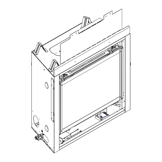
Page 74: Service Parts
SL-550METRO C. Service Parts Beginning Manufacturing Date: May 2009 Service Parts Diagram Ending Manufacturing Date: ______ Part number list on following page. Heat & Glo • SL-550METRO, SL-550METRO-LP • 2185-900 Rev. D • 8/09... - Page 75 Conversion Kit LP LPK-550METRO Pilot Orifi ce NG 593-528 Pilot Orifi ce LP 593-527 Regulator NG NGK-DXF Regulator LP LPK-DXF Additional service part numbers appear on following page. Heat & Glo • SL-550METRO, SL-550METRO-LP • 2185-900 Rev. D • 8/09...
- Page 76 Module Wire Assembly 593-590A 3 Volt Transformer 593-593A Orifi ce NG (#44) 582-844 Orifi ce LP (#55) 582-855 Flex Tube Assembly 7000-156 Jumper Wires, 2 in, male to male 2106-206 Heat & Glo • SL-550METRO, SL-550METRO-LP • 2185-900 Rev. D • 8/09...
-
Page 77: Contact Information
6748942, 6769426, 6774802, 6796302, 6840261, 6848441, 6863064, 6866205, 6869278, 6875012, 6880275, 6908039, 6919884, D320652, D445174, D462436; (Canada) 1297749, 2195264, 2225408, 2313972; (Australia) 780250, 780403, 1418504 or other U.S. and foreign patents pending. Printed in U.S.A. - Copyright 2009 Heat & Glo • SL-550METRO, SL-550METRO-LP • 2185-900 Rev. D • 8/09...
Need help?
Do you have a question about the SL-550METRO-LP and is the answer not in the manual?
Questions and answers