Table of Contents
Advertisement
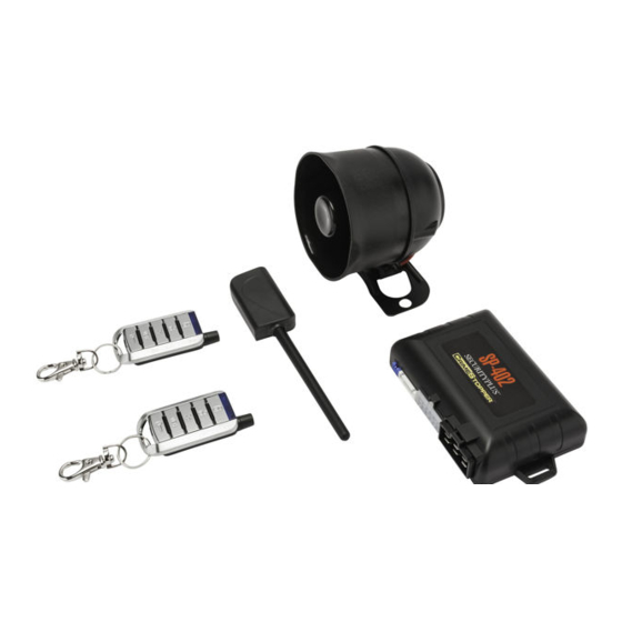
Combo Alarm & Remote Engine Starting System
CONGRATULATIONS on your choice of the SP-402 by Crimestopper Security Products Inc. This booklet contains the
information necessary for operating your system. If any questions arise, contact your installation dealer or
Crimestopper Security Products Inc.
CONTACT INFORMATION:
TECHNICAL SUPPORT (800)-998-6880
Monday - Friday 8:00am - 4:30pm Pacific
Website: www.crimestopper.com
CRIMESTOPPER
SECURITY PRODUCTS, INC.
1770 S. TAPO STREET
SIMI VALLEY, CA. 93063
REV 09-2012
SP-402
OPERATING INSTRUCTIONS
INTRODUCTION
This device complies with FCC Rules part 15. Operation is subject
to the following two conditions: 1) This device may not cause
interference, and (2) this device must accept any interference that
may be received, including interference that may cause undesired
operation. The manufacturer is not responsible for any radio or TV
interference
equipment. Such modification could void the user's authority to
operate the equipment.
caused
by
unauthorized
modification
to
this
Advertisement
Table of Contents

Related Manuals for CrimeStopper SP-402


Summary of Contents for CrimeStopper SP-402
-
Page 1: Operating Instructions
Combo Alarm & Remote Engine Starting System OPERATING INSTRUCTIONS INTRODUCTION CONGRATULATIONS on your choice of the SP-402 by Crimestopper Security Products Inc. This booklet contains the information necessary for operating your system. If any questions arise, contact your installation dealer or Crimestopper Security Products Inc. -
Page 2: Remote Start
USING THE REMOTE TRANSMITTER VEH 1 = Blue LED VEH 2 = Red LED Lock / Arm Remote AUX Outputs Unlock / Disarm AUX 1 = Trunk + Lock AUX 2 = Trunk + Unlock Trunk Release AUX 3 = Trunk + Start AUX 4 = Lock + Start Vehicle Select Remote Start... - Page 3 QUICK CHART BUTTON FUNCTIONS Button Button Button Options Button Button Functions Button Options Functions Press and Hold 2 Selects between Lock Doors & Arm Press and Hold for 2 Seconds for Panic Vehicle #1 and System seconds Mode Vehicle #2 Unlock Doors &...
- Page 4 OPERATING INSTRUCTIONS - ALARM ARMING / LOCKING Press the Lock Button on the remote control. The System will arm emit one siren chirp, one light flash, and the LED will begin to flash. Power locks will lock (if equipped). Starter disable circuit will turn on. The 2-Way LCD Pager will beep once while displaying a Locking symbol.
- Page 5 OPERATING INSTRUCTIONS - ALARM ALARM TRIGGERS If there is an intrusion into the vehicle, a hard impact to the body or the ignition is turned on, the alarm will sound and flash the lights for 1 minute. After 1 minute, the trigger cycle will automatically stop and alarm will remain armed to continue protecting the vehicle.
- Page 6 OPERATING INSTRUCTIONS - ALARM REMOTE PANIC PROTECTION To sound the alarm in an emergency or to draw attention to your vehicle, press and hold the Lock button for at least 3 seconds until the siren / horn sounds. Press the Unlock button to reset panic mode. The LCD display will flash most of the icons and emit 10 beeps when the Panic Mode is triggered.
- Page 7 OPERATING INSTRUCTIONS - ALARM PRIOR INTRUSION ALERT This system will notify you if the alarm was triggered while you were away. Upon disarming, there will be four additional siren chirps after the two normal disarm chirps. Check your vehicle for any signs of a break in or tampering.
- Page 8 REMOTE ENGINE CONTROL REMO TE ENGINE CONTROL REMOTE START & Trunk Release – Button Press Selection (Option # 8) To eliminate the possibility of accidentally opening the trunk or starting the vehicle, there are (3) options for button press selection. This option will allow you to change whether the Remote starter and Trunk release activate by a: 4.
- Page 9 REMOTE ENGINE CONTROL UNSUCCESSFUL REMOTE START In the event that the engine does not start on the first attempt, the system shuts down for a few seconds, then attempts to restart the engine a 2 and 3 time. For hard starting engines, the unit will allow a starter crank time of up to4 seconds maximum.
- Page 10 IDLE DOWN MODE IDLE DOWN MODE (Option # 26 – 10, 20, 30 minutes or Infinity Run) This mode allows the unit to take over operation of your idling, parked vehicle while the ignition key is removed and you exit the vehicle. The vehicle is put into a remote running condition before you exit and it will remain running for the programmed run time, until you return, or until the remote start button is pressed.
- Page 11 TIMED SELF STARTING MODE TIMED SELF START MODE This mode allows the vehicle to be programmed to self-start every 4 hours and run for the programmed run time. This can be helpful during extremely cold conditions where engine or fluid freeze-up is a concern. !!THE VEHICLE MUST BE OUTDOORS OR IN A WELL VENILATED AREA!! TIMED SELF-START MODE –...
- Page 12 TURBO TIMER MODE TURBO TIMER MODE (Option # 31) The optional Turbo Timer mode allows the CoolStart system to keep a Turbo or Turbo Diesel vehicle running for 1, 3 or 5 minutes [selectively] after you remove the key and exit the vehicle. This is handy for turbo cool- down without the need for expensive turbo timers.
- Page 13 MANUAL TRANSMISSION MODE MANUAL TRANSMISSION EXIT PROCEDURE (Option #15-1, 15-3 and 15-4) This system features a Manual Transmission Mode. When exiting the vehicle, there is safety check out procedure required for the manual transmission mode to work. There are 3 choices of operation, 1.
- Page 14 ANTI CARJACK PROTECTION CARJACK PROTECTION (Option 32-1) This optional feature requires installation of a hidden momentary button or an On/Off switch for Carjack protection. Carjack provides protection while driving your vehicle. If a Carjacker opens, any door with the ignition on, the system arms. When the door closes, the parking lights will flash 2 times and the LED will begin to flash rapidly to confirm the beginning of a Carjack countdown.
- Page 15 ALARM TRIGGER DIAGNOSTICS This systems includes disarm diagnostics, through the LED light, that will help in determining what caused the last trigger of the alarm system. This is a valuable tool in determining how the vehicle was tampered with or if there is a false alarm problem, in which case you can make the necessary adjustments to correct the problem.
- Page 16 TRANSCEIVER / REMOTE CONTROL PROGRAMMING Note: All transmitter codes must be learned at time of programming! This system learns up to 4 different transmitter codes. 1. Turn ignition key to the ON position. 2. Press Programming button 4 times, then after a few seconds the unit flashes the parking lights 4 times. 3.
- Page 17 2 VEHICLE OPERATION 2 VEHICLE CONTROL A single Remote Control can control two different vehicles. To set up the 2-Vehicle operation you must first program your remotes to Vehicle #2. Follow the “Transmitter Programming” steps (Pg. 12) at the second vehicle and learn YOUR remote, along with vehicle #2’s existing remotes.
- Page 18 BATTERY REPLACEMENT To Replace the Battery: The Remote Control uses two CR-2025 Lithium 3 Volt Batteries. Simply remove the Phillips screw located behind key ring (see diagram below). The top cover snaps apart from the back cover. Slide old batteries out and remove plastic cover.
- Page 19 Databus modules are used to communicate with the vehicles computer at the OBD2 Data connector or Canbus wires. This reduces installation error. Crimestopper Systems with DP Series have a direct Data Port Plug-In for the Databus bypass module. This eliminates conventional wiring between the Alarm/Remote Starter and the bypass interface module.
- Page 20 Crimestopper Security Products Inc. 1770 So. Tapo Street Simi Valley, CA 93063 ONLINE TECHNICAL SUPPORT (800) 998-6880 www.crimestopper.com www.crimestopper.com ©2012 Crimestopper Security Products...
Need help?
Do you have a question about the SP-402 and is the answer not in the manual?
Questions and answers