Table of Contents
Advertisement
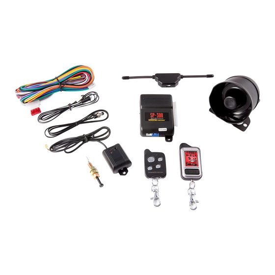
2-WAY REMOTE CONTROL ALARM SYSTEM
CONGRATULATIONS on your choice of an Remote Alarm System by Crimestopper Security Products Inc.
This booklet contains the information necessary for installing, using, and maintaining your alarm system. If
any questions arise, contact your installation dealer or Crimestopper Security Products Inc. at the Tech
Support number below.
*IMPORTANT INFORMATION: Primary and Optional Features:
-PRIMARY: These are features that must be connected in order for the system to operate properly; i.e. the
Siren, L.E.D., +12V Power, Ground, Door pin, Flashing lights Override/Program/Valet Button etc.
-OPTIONAL: These are features to be connected if desired or agreed upon by the installing dealer. These
features may also require additional parts and/or labor fees. Consult with your installer beforehand; i.e. Door
Locks, Starter disable, Hood/Trunk trigger, and Auxiliary Remote Outputs etc.
This installation book is designed for the installer or individual with an existing understanding of automotive
electrical systems, along with the ability to test and connect wires for proper operation. To ease installation,
we suggest that you READ THIS MANUAL before beginning your installation. This book is provided as a
GENERAL GUIDLINE and the information contained herein may differ from your vehicle.
TECH SUPPORT
Mon-Fri 8:00 AM-4:30 PM Pacific Time
(800) 998-6880
REV. 12-2008
FS-30
OPERATING INSTRUCTIONS
INTRODUCTION
This device complies with FCC Rules part 15. Operation is subject to
the following two conditions: 1) This device may not cause interference,
and (2) this device must accept any interference that may be received,
including interference that may cause undesired operation.
manufacturer is not responsible for any radio or TV interference caused
by unauthorized modification to this equipment. Such modification
could void the user's authority to operate the equipment.
The
Advertisement
Table of Contents

Related Manuals for CrimeStopper Fortress FS-30


Summary of Contents for CrimeStopper Fortress FS-30
-
Page 1: Operating Instructions
TECH SUPPORT Mon-Fri 8:00 AM-4:30 PM Pacific Time (800) 998-6880 REV. 12-2008 FS-30 INTRODUCTION This device complies with FCC Rules part 15. Operation is subject to the following two conditions: 1) This device may not cause interference, and (2) this device must accept any interference that may be received, including interference that may cause undesired operation. -
Page 2: Table Of Contents
TABLE OF CONTENTS Operation Cautions & Warnings……..…………..……………………………………………………………………2 The Remote Controls………………………………...……………………..……………………….…….……..…..3-4 Quick Chart Button Functions…………………………...……………………………………………….……...5 Operating Instructions………………………..……………….…….………………….…….…………...……...…6-9 Car Jack Protection..…………..…………..……………………………………………...…………………..…….…10 Transmitter Programming.………………………………….…………………………….……………...………..…11 2 Vehicle Programming…………..…………..………………….…………………………….…………….……..…12 Battery Replacement…….……………………………………...……………………………..……………..………13 Data Port Diagram …………………………………………………………………………………………………..…14 OPERATION CAUTIONS & WARNINGS CRIMESTOPPER SECURITY PRODUCTS, INC. and its VENDORS shall not be liable for any accident resulting from the use of this equipment. -
Page 3: The Remote Controls
2-WAY - PAGER / REMOTE TRANSCEIVER: 12:00 DISARM / ARM / UNLOCK LOCK THE REMOTE CONTROLS 1-WAY - SIDEKICK REMOTE: ARM / TRUNK LOCK SILENT SILENT ARM / DISARM VEH 1 / VEH 2 CLOCK SET DISARM / UNLOCK VEH 1 / VEH 2 TRUNK... -
Page 4: The Remote Controls
1-WAY - SIDEKICK REMOTE: The 1-Way sidekick remote adds flexibility to your system. You can have the convenience of operating your system without needing to carry the larger pager remote. The Sidekick remote has less range and offers all of the same operation features except for page-back confirmation. -
Page 5: Quick Chart Button Functions
QUICK CHART BUTTON FUNCTIONS Button Button Functions Lock Doors & Arm System Unlock Doors and Disarm System Trunk Release Aux # 1 Silent Arm / Disarm Aux Selects between Vehicle #1 / Vehicle #2. Press & hold 2 Sec. Lock = Increase, Unlock = Decrease, Trunk = CLOCK SETUP: Next, SLT = Beep with button press, VEH = Exit Button Options... - Page 6 OPERATION INSTRUCTIONS ARMING To arm the alarm and lock the doors, press the Lock button on the transmitter. You will hear a single siren chirp and the lights will flash once. The system will arm, the doors will lock and the starter will be disabled if these optional features are installed.
-
Page 7: Operating Instructions
OPERATING INSTRUCTIONS ARM / DISARM WITH IGNITION ON (PROGRAM OPTION #15) This feature allows the system to be armed or disarmed while the ignition is in the ON position or vehicle is running. The feature is disabled by default and should not be used under normal operating conditions. On an installation with an add-on remote start module, this option can be enabled to allow the system to be armed or disarmed when the vehicle has been remote started (Ignition will be ON). -
Page 8: Cautionary Note
EMERGENCY OVERRIDE / DISARM If you have lost the transmitter or it stops working for any reason and the Alarm is armed, you will have to open the door with the key, which will activate the alarm. Turn the ignition on and press the override/program button for about 5 seconds (until siren stops). - Page 9 OPERATING INSTRUCTIONS VALET MODE (Solid LED) To disable the Alarm system for vehicle service or otherwise, turn the ignition on and press the override/program button 4-5 seconds until the dash LED turns on solid and you hear (1) siren chirp. Repeat the process to exit VALET mode and the system will chirp (2) times and the LED will turn off.
-
Page 10: Carjack Protection
CARJACK PROTECTION ACTIVE CARJACK This feature provides Active Carjack protection and must be enabled before use through Alarm programming option (14) See page 10. When the Ignition is on (vehicle is running), press and hold button #3 (AUX) for 3 seconds. Parking lights will flash TWICE to confirm the Carjack countdown sequence. -
Page 11: Transmitter Programming
NOTE: All transmitters must be learned at the time of programming. This system can learn up to 4 remotes. 1. Turn key to the ON position and press program button 4 times. 2. After a short delay, the unit will flash the parking lights 4 times, Siren 4 times, Horn 4 times and status LED will be on solid. -
Page 12: Vehicle Control
2 VEHICLE OPERATION / PROGRAMMING 2 VEHICLE CONTROL Your remotes have the ability to control a second vehicle with a Crimestopper system installed. To set up the 2-Vehicle operation you must first program your remotes to Vehicle #2. Follow the “Transmitter Programming”... -
Page 13: Low Battery Warning
BATTERY REPLACEMENT LOW BATTERY WARNING The 2-Way LCD remote has a low battery warning system. When the battery voltage is low, the LCD Pager Remote will show a low voltage icon. recommend replacing the battery for proper operation. To replace the battery: Simply unlatch and slide open the battery door on the back of the remote. -
Page 14: Data Port Diagram
Some vehicles require a Databus Module to Bypass the factory Immobilizer and operate the keyless entry Databus modules are used to communicate with the vehicles computer at the OBD2 Data connector or Canbus wires. This reduces installation error. Crimestopper Systems with DP Series have a direct Data Port Plug-In for the Databus bypass module.
Need help?
Do you have a question about the Fortress FS-30 and is the answer not in the manual?
Questions and answers