Table of Contents
Advertisement
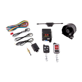
2-WAY REMOTE CONTROL ALARM SYSTEM
CONGRATULATIONS on your choice of a Remote Alarm System by Crimestopper Security Products Inc.
This booklet contains the information necessary for installing, using, and maintaining your alarm system. If
any questions arise, contact your installation dealer or Crimestopper Security Products Inc. at the Tech
Support number below.
*IMPORTANT INFORMATION: Primary and Optional Features:
-PRIMARY: These are features that must be connected in order for the system to operate properly; i.e. the
Siren, L.E.D., +12V Power, Ground, Door pin, Flashing lights Override/Program/Valet Button etc.
-OPTIONAL: These are features to be connected if desired or agreed upon by the installing dealer. These
features may also require additional parts and/or labor fees. Consult with your installer beforehand; i.e. Door
Locks, Starter disable, Hood/Trunk trigger, and Auxiliary Remote Outputs etc.
This installation book is designed for the installer or individual with an existing understanding of automotive
electrical systems, along with the ability to test and connect wires for proper operation. To ease installation,
we suggest that you READ THIS MANUAL before beginning your installation. This book is provided as a
GENERAL GUIDLINE and the information contained herein may differ from your vehicle.
TECH SUPPORT
Mon-Fri 8:00 AM-4:30 PM Pacific Time
(800) 998-6880
REV. 12-12-2008
SP-300
INSTALLATION INSTRUCTIONS
INTRODUCTION
This device complies with FCC Rules part 15. Operation is subject to
the following two conditions: 1) This device may not cause interference,
and (2) this device must accept any interference that may be received,
including interference that may cause undesired operation.
manufacturer is not responsible for any radio or TV interference caused
by unauthorized modification to this equipment. Such modification
could void the user's authority to operate the equipment.
The
Advertisement
Table of Contents

Subscribe to Our Youtube Channel
Related Manuals for CrimeStopper SP-300


Summary of Contents for CrimeStopper SP-300
- Page 1 CONGRATULATIONS on your choice of a Remote Alarm System by Crimestopper Security Products Inc. This booklet contains the information necessary for installing, using, and maintaining your alarm system. If any questions arise, contact your installation dealer or Crimestopper Security Products Inc. at the Tech Support number below.
-
Page 2: Table Of Contents
TABLE OF CONTENTS Installation Cautions & Warnings..…….……………………………….……………………………………….……2 Control Module & Component Mounting ……………...……………………..……………………….…….…..…..3 LED and Valet Programming Button………………………………………………………………………………….3 Wiring………………………………………………………………………..…………………..………….….…….….4-5 SHOCK SENSOR Wiring…….…………….………….….…..…………………………………………………………6 Power Door Lock Wiring……………………………………………………….………………………….…...….…6-7 Transmitter Programming………………………………………………………………………………………………8 Vehicle Programming..…………………..………………………….……...9 Option Programming…………………………………………….…….………………….…….…………...….…10-13 Antenna Diagram..………………………………………………..……………………………..……………..………14 Wiring Diagram..…………………………………………………..……………………………..……………..………15 Data Port Diagram …………………………………………………………………………………………………..…16 INSTALLATION CAUTIONS &... -
Page 3: Control Module & Component Mounting
CONTROL MODULE & COMPONENT MOUNTING DO NOT Mount the control module in the engine compartment or where the wiring harness can become entangled with moving parts such as brake/gas/clutch pedals, or the steering column! The alarm control module should be mounted in a concealed location. The Placement of the module will affect the distance from which the remote transmitter can control the unit. -
Page 4: Green Wire: Negative Door Trigger
WIRING GREEN WIRE: (-) NEGATIVE DOOR TRIGGER Identify the wire that reads ground when any door is open and 12 volts when all doors are closed. Some vehicles may have isolated door triggers. In this case you may need to run additional wires from other doors or go directly to the wire that triggers the vehicle’s interior dome light. - Page 5 WIRING BLACK/WHITE WIRE: (-) NEGATIVE DOME LIGHT ILLUMINATION OUTPUT (Optional, requires a relay) This wire provides a (-) negative ground when the system is disarmed to activate a vehicles dome light circuit. We recommend the use of a relay for this connection. Connect Black/White to terminal #85 of relay. Connect terminal #86 to fused constant +12V.
-
Page 6: Shock Sensor Wiring
WIRING: SHOCK SENSOR SHOCK SENSOR: The sensor supplied with this system does not require any additional wiring. Simply mount the sensor in a suitable location, plug it in, and adjust the sensitivity. There are 2 LED’s on the shock sensor to assist you in adjusting sensitivity. The Green LED indicates the “Warn Away” level and the Red LED indicates a full alarm shock sensor violation. -
Page 7: Power Door Lock Wiring
POWER DOOR LOCK WIRING NEGATIVE TRIGGER DOORLOCK WIRING GREEN BLUE REVERSE POLARITY DOOR LOCK WIRING GREEN BLUE MASTER SWITCH POSITIVE TRIGGER DOORLOCK WIRING GREEN BLUE FACTORY POWER LOCKING RELAYS AFTERMARKET MOTOR/DOOR LOCK WIRING GREEN FUSED +12V BLUE FUSED +12V FACTORY POWER LOCKING RELAYS... -
Page 8: Transmitter Programming
NOTE: All transmitters must be learned at the time of programming. This system can learn up to 4 remotes. 1. Turn key to the ON position and press program button 4 times. 2. After a short delay, the unit will flash the parking lights 4 times, Siren 4 times, Horn 4 times and status LED will be on solid. -
Page 9: Nd Vehicle Programming
2 VEHICLE TRANSMITTER PROGRAMMING PROGRAMMING SECOND VEHICLE: To set up your remote, follow the “Transmitter Programming” steps 1 and 2 (above) In step #3 press the side button on YOUR remote first, for 2-way press and hold for side button until the “2” Icon show on the remote, then press the Lock and Unlock button. -
Page 10: Option Programming
1. Turn the Ignition ON and press the Override/Program button 5 times. 2. After a short delay, the parking lights will flash 5 times, Siren 5 times, Horn 5 times and status LED will be on solid. 3. Within the next few seconds, press the Override/Program button [again] the number of times that corresponds to the options chart below. - Page 11 OPTION PROGRAMMING NOTE: Options can be instantly restored to Factory Default Values. To restore default values: Perform step #1 (See page 10), then press button 3 (trunk). The siren and horn will chirp 4 times and lights will flash 4 times. Turn OFF Ignition. All programming options will be restored to * Default * values (See page 10).
- Page 12 OPTION PROGRAMMING 6. ACTIVE RE-ARMING Active Re-arming allows the system to re-arm itself 30 seconds after disarmed with the transmitter if a door has not been opened. This is handy if the vehicle is accidentally disarmed (via the Transmitter in your pocket) without you knowing it.
- Page 13 OPTION PROGRAMMING Cont. 14. CARJACK FEATURES This option controls the unit’s Car Jack features. Enable or Disable Carjack (Turn ON or OFF) with this option. 15. Lock/Unlock or Arm/Disarm with Ignition ON This option allows you Arm and Disarm the system with the Ignition ON. This is used when there is a remote starter added to the system.
-
Page 14: Antenna Diagram
ANTENNA DIAGRAM Antenna should be located at top of widow at least one inch away from metal surface. ANTENNA LOCATIONS WINDSHIELD... -
Page 15: Wiring Diagram
(-) REMOTE OUTPUT 1 RELAY BLUE (-) HOOD/TRUNK TRIGGER (-) NEG. BLACK/WHITE PIN SWITCH (-) DOME LIGHT OUTPUT DOME LIGHT WIRING DIAGRAM BLUE GREEN SP-300 BROWN/WHITE (-) HORN HONK OUTPUT STATUS LED SHOCK SENSOR ANTENNA FUSE +12V POWER BATTERY PARKING LIGHTS... -
Page 16: Data Port Diagram
Bypass Module Module Not Included www.crimestopper.com Phone (800) 998-6880 FAX (805) 581-9500 © 2008 Crimestopper Security Products DATA PORT DIAGRAM Data wire 9 10 11 12 13 14 15 16 OBD connector iDATA LINK CABLE Data Port ONLINE TECHNICAL SUPPORT...
Need help?
Do you have a question about the SP-300 and is the answer not in the manual?
Questions and answers