
Related Manuals for Eaton PXL Series


Summary of Contents for Eaton PXL Series
- Page 1 Installation and Operation Manual for Powerware Instruction Manual: PXL Series Surge Protective Device IM01005001E IM 01005001E For more information visit: www.eatonelectrical.com Effective 01.06...
-
Page 2: Table Of Contents
PXL Series Installation Instruction Manual Page 2 Effective: January 2006 and Operation Manual PXL Installation Manual Table of contents Description Page Section 1 Introduction ..........3 Section 2 Installation Procedure......3 Section 3 Operating Features........6 Section 4 Troubleshooting ........7 Section 5 Warranty and Technical Assistance..15 IM 01005001E information visit: www.eatonelectrical.com... -
Page 3: Section 1 Introduction
The hi-pot tester that the line and neutral connection are The PXL series of Surge Protective outputs a high voltage signal at low removed rather than the ground Devices (referred to as PXL from this current that will shut down if a short connection. - Page 4 PXL Series Installation Instruction Manual Page 4 Effective: January 2006 and Operation Manual 2.2 Installation Recommendation The unit is provided with 8 knockout holes - 3 on each side and 2 on the for PXL bottom. Remove the knockout closest to...
- Page 5 PXL Series Installation Instruction Manual and Operation Manual Page 5 Effective: January 2006 2.7.2 PXL Installation Wiring Diagrams Figure 1. Single Phase (Split-Phase): 3 Wire + Ground/PE - Voltage Code: 240S Figure 3. 3 Phase Wye: 4 Wire + Ground/PE - Voltage Codes: 208Y, 480Y Figure 2.
-
Page 6: Section 3 Operating Features
PXL Series Installation Instruction Manual Page 6 Effective: January 2006 and Operation Manual 2.8 Ordering Guidelines Table 4. PXL Ordering Guidelines Catalog # PXLXXXYYYYZK YYYY Surge Rating Voltage Display Option (kA) Configuration 208Y S – Standard Monitor 240D NEMA 1, 240S P –... -
Page 7: Section 4 Troubleshooting
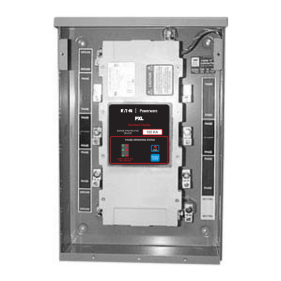
PXL Series Installation Instruction Manual and Operation Manual Page 7 Effective: January 2006 3.2.2 Premium Display Section 4 Troubleshooting 3.2 Monitoring Options The Premium display option has the 4.1 Life expectancy 3.2.1 Standard Display same features as the Standard plus a multifunction LCD screen for displaying Note: The PXL is not field repairable. - Page 8 PXL Series Installation Instruction Manual Page 8 Effective: January 2006 and Operation Manual 4.3 Common Causes of SPD Problems SPDs are applied to electrical systems to mitigate surges, transients, impulse or spikes. By definition, surges are random high magnitude short-term voltage...
- Page 9 PXL Series Installation Instruction Manual and Operation Manual Page 9 Effective: January 2006 200KA Alarm Disabled if Red LED Illuminated LEDs Green = Good Red = Bad or Problem Alarm Disabled Button Pxl Power System Standard Display Table 5. PXL Standard Display...
- Page 10 PXL Series Installation Instruction Manual Page 10 Effective: January 2006 and Operation Manual Table 5. PXL Standard Display (Continued) PXL Standard Display Symptom Solution Cause ■ Red LEDs ON, Lost Neutral Confirm Neutral connection on buzzer ON. (Condition 1) SPD on lower left hand side unit.
- Page 11 Red = Bad or Problem Voltage Display VAB VBC VCA Pxl Power System Premium Display Note: Refer to the PXL Series installation manual for detailed information on the Premium display menu features. Table 6. PXL Premium Display PXL Premium Display Symptom...
- Page 12 PXL Series Installation Instruction Manual Page 12 Effective: January 2006 and Operation Manual Table 6. PXL Premium Display (Continued) PXL Premium Display Symptom Cause Solution ■ All red LEDs ON, Lost Neutral Check Neutral connection incorrect voltage display. (Condition 1) on SPD at lower left hand side.
- Page 13 PXL Series Installation Instruction Manual and Operation Manual Page 13 Effective: January 2006 Table 6. PXL Premium Display (Continued) PXL Premium Display Symptom Cause Solution ■ Check terminal voltage All green LEDs ON, Incorrect calibration with digital multimeter, Buzzer OFF, incorrect voltage display.
- Page 14 Instruction Manual PXL Series Installation Page 14 Effective: January 2006 and Operation Manual 100KA VAB VBC VCA 4.5.2 Premium Display 4.5 PXL Premium Display Calibration Procedure Steps Calibration Procedure Shut OFF power to the unit. Press and hold the STEP button. Do...
-
Page 15: Section 5 Warranty And Technical Assistance
Section 5. Warranty Eaton Powerware warrants these products for a period of 10 years from the date of delivery to the purchaser to be free from defects in both workmanship and materials. Eaton Powerware assumes no risk or liability for results of the use of the products purchased from it, including but without limiting the generality of the foregoing: (1) The use in combination with any electrical or electronic components, circuits, systems, assemblies or any other materials or substances;... - Page 16 1000 Cherrington Parkway Moon Township, PA 15108-4312 Tel: 1-800-525-2000 www.eatonelectrical.com © 2006 Eaton Corporation All Rights Reserved Printed in USA Publication No. IM01005001E...
Need help?
Do you have a question about the PXL Series and is the answer not in the manual?
Questions and answers