Eaton SP Series, PX Series Manual
- Installation and operation manual (4 pages)
Advertisement
Introduction
This manual describes how to install a surge protective device (SPD) in parallel (shunt) across the AC supply of the following types of electrical systems:
- Split-phase
- Three-phase wye
- Three-phase delta
The SPD is designed to be installed on service entrance, branch panels, and/or individual equipment disconnects, and functions to protect sensitive electronic equipment from damaging voltage transients. The connecting wires do not carry supply current. Instead, they carry only short-duration currents that are associated with a transient event.
These instructions do not cover all details, variations, or combinations of the equipment, its storage, delivery, installation, checkout, safe operation, or maintenance. If you require further information regarding a particular application or installation that is not covered in this manual, please contact Eaton's Power Quality Technical Support at 1-800-809-2772, option 5, option 2.
Safety precautions
A licensed/qualified electrician must complete all instructions described in this manual in accordance with the U.S. National Electrical Code, state and local codes, or other applicable country codes. All electrical codes supersede these instructions. Suitable for use on a circuit capable of delivering not more than 200,000 rms symmetrical amperes.

SHOCK HAZARD—DO NOT OPEN.
IMPROPER INSTALLATION CAN CAUSE DEATH, INJURY, AND/OR EQUIPMENT DAMAGE.
FOLLOW ALL WARNINGS AND CAUTIONS. COMPLETELY READ AND UNDERSTAND THE INFORMATION IN THIS INSTRUCTION MANUAL BEFORE ATTEMPTING TO INSTALL OR OPERATE THIS EQUIPMENT.
ONLY LICENSED/QUALIFIED ELECTRICIANS WHO ARE TRAINED IN THE INSTALLATION AND SERVICE OF ELECTRICAL DEVICES ARE TO INSTALL AND SERVICE THIS EQUIPMENT.
USE APPROPRIATE SAFETY PRECAUTIONS AND EQUIPMENT FOR ARC FLASH PROTECTION.
DURING NORMAL OPERATION, HAZARDOUS VOLTAGES ARE PRESENT INSIDE THE SPD.
WHEN SERVICING THE SPD, FOLLOW ALL SAFE WORK PRACTICES TO AVOID ELECTRICAL SHOCK.

NO SERVICEABLE PARTS

DO NOT PERFORM A HIGH-POT TEST WITH THE SPD CONNECTED TO THE ELECTRICAL SYSTEM. FAILURE TO DISCONNECT THE SPD DURING A HIGH-POT TEST WILL RESULT IN DAMAGE TO THE SPD
Installation
Refer to Table 1 and Table 2 and look at the label on the SPD to verify that the SPD's voltage rating and wiring configuration matches that of the electrical system. Use an AC voltmeter to measure the system's line voltage to ensure that the correct model of SPD is being installed. Damage to the SPD may result if it is connected to an electrical system of a higher voltage or different wiring configuration.

Mounting
The SPD can be mounted directly to the electrical panel, or to a wall or DIN rail with the addition of an optional mounting kit, catalog number SP1MNTGKIT.
NOTICE
CHOOSE A MOUNTING LOCATION FOR THE SPD THAT PROVIDES THESHORTEST AND STRAIGHTEST POSSIBLE WIRING (LEAD LENGTH) FROM THE SPD TO THE ELECTRICAL SYSTEM CONNECTIONS. EXCESSIVE LEAD LENGTH AND SHARP BENDS WILL DEGRADE SPD PERFORMANCE.
IF THE ELECTRICAL SYSTEM USES AN ISOLATED GROUND, THE SPD MUST BE ISOLATED FROM GROUND USING INSULATED CONDUIT FITTINGS.
WHEN USING CONDUIT, AVOID USING 90° ELBOWS AND KEEP THE CONDUIT RUN AS SHORT AND STRAIGHT AS POSSIBLE
Conduit installation

Mount the SPD directly to the electrical panel using a 1/2-inch locknut as shown in Figure 1.

When mounting the SPD outdoors, use weatherproof conduit and fittings to maintain the enclosure's NEMA 4 rating. See Figure 2.
Wall mounting

See Figure 3
Mount the SPD directly on a wall using the SPD's optional SP1MNTGKIT as follows:
- Screw the wall bracket to the wall or other mounting surface using two #10 screws of the appropriate type (not provided) with the large hole in the bracket at the top.
- Thread the lead wires from the SPD through the large hole and insert the integrated hub into the large hole with the hub pointed upward.
- Use the locknut (provided) to secure the SPD hub to the bracket.
For DIN rail mounting
See Figure 3
Mount the SPD directly on the DIN rail using the SPD's optional SP1MNTGKIT as follows:
- Snap the DIN rail clip into the two smallest holes in the mounting bracket.
- Thread the lead wires from the SPD through the large hole in the bracket and insert the integrated hub into the large hole.
- Use the locknut (provided) to secure the SPD hub to the bracket.
- Snap the SPD and bracket to the DIN rail (not provided) with the hub pointed upward.
Wiring
NOTICE
BE SURE TO FOLLOW ALL NATIONAL, STATE, AND LOCAL ELECTRICAL CODES WHEN MAKING WIRING CONNECTIONS.
WHEN CONNECTING THE WIRES FROM THE SPD TO THE ELECTRICAL SYSTEM, CUT THE WIRES AS NECESSARY TO KEEP THEM AS SHORT AS POSSIBLE.
TO MAXIMIZE THE SPD'S PERFORMANCE, TWIST AND BIND THE WIRES TOGETHER TO REDUCE THE IMPEDANCE OF THE WIRE (ONE TWIST/INCH).
IF THE SYSTEM UTILIZES AN ISOLATED GROUND, THE SPD'S GROUND WIRE MUST BE CONNECTED TO THE SYSTEM'S ISOLATED GROUND BUS.
- Locate the electrical system's applicable wiring diagram (Figure 4). Reference this wiring diagram as necessary in Steps 2, 3, and 4.

- Connect the SPD's ground wire (green) to the system's ground connection (delta only).
- Connect the SPD's neutral wire (white) to the system's neutral connection (not required for three-phase delta systems).
- Connect the SPD's phase A, B, and C wires (black) to the system's corresponding phase A, B, and C connections according to applicable national, state, and local electrical codes.

Operation
Power-up and system checkout
Apply system power. The LED should light.
If the connected LED does not light, remove power, check connections, and test again. If the LED still does not light, contact your supplier.
Routine operation
After system power has been applied, the SPD automatically begins to protect downstream electrical devices from damaging voltage transients.
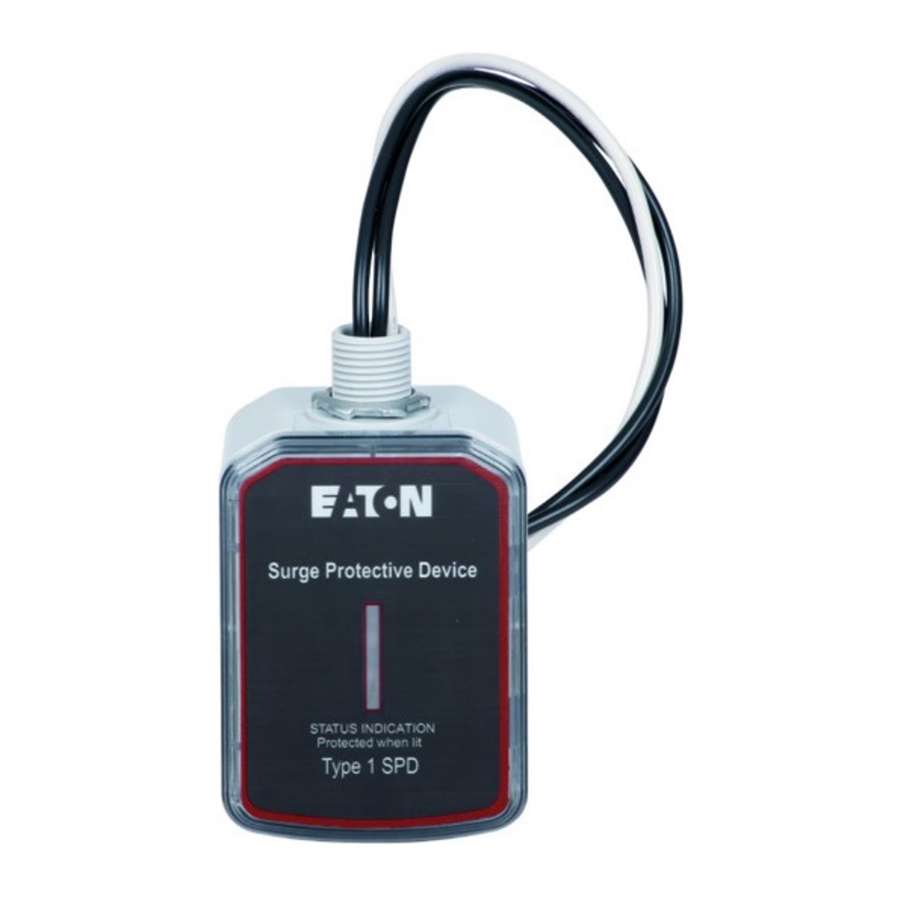
With all phase voltages present, the LED indicator reports the status of the protection elements and is active when all of them are intact and providing protection. Any loss of protection is signaled when the LED extinguishes.
The device is not repairable and contains no user serviceable parts. If the unit fails, as evidenced by the LED turning OFF, the unit must be replaced. Please contact your distributor as the SPD may be under warranty.
DO NOT use the Suppression Circuit Status LEDs as an indication of the presence or absence of system phase voltages.
Specifications
| Description | Ratings |
| Surge current capacity per phase | 50 kA, 75 kA |
| Nominal discharge current (In) | 120/240 V, 120/208 V, 277/480 V, 240 V, 480 V: 20 kA 347/600 V, 600 V: 10 kA |
| Short circuit current rating (SCCR) | 200 kA |
| SPD type | Type 1 (can also be used in Type 2 applications) |
| System voltages available (Vac) | |
| Single split-phase | 120/240 |
| Three-phase wye | 120/208, 277/480, 347/600 |
| Three-phase delta | 240, 480, 600 |
| Protection modes | |
| Single split-phase and three-phase wye | L-N, L-L |
| Three-phase delta | L-G, L-L |
| Maximum continuous operating voltage (MCOV) | |
| 120/240, 120/208 V | 150 L-N, 300 L-L |
| 277/480 V | 320 L-N, 640 L-G |
| 347/600 V | 420 L-N, 840 L-G |
| 240 V delta | 300 L-G, 300 L-L |
| 480 V delta | 640 L-G, 640 L-L |
| 600 V delta | 840 L-G, 840 L-L |
| Input power frequency | 50/60 Hz |
| Enclosure rating | NEMA 4 |
| Operating temperature | –20°C through +50°C (–4°F through +122°F) |
| Operating humidity | 5% through 95%, noncondensing |
| Operating altitude | Up to 16,000 ft (5000 m) |
| Agency certification and approvals | UL 1449 5th Edition Type 1 and Type 2 SPD CSA -22.2 No. 269.1-17 2nd Edition |
| Warranty | 2 years |
| UL 96A Compliant | Yes |
| NFPA 780 Compliant | Yes |
| Wire length and AWG | Factory prewired with 24 inches of 12 AWG wire |
Warranty
For help on troubleshooting the SPD, or for warranty information, call 1-800-809-2772, option 5, sub-option 2. Repair or replacement units will be returned collect. If Eaton finds the return to be a manufacturer's defect, the product will be returned prepaid.
For technical support, please call 1-800-809-2772.
Eaton
1000 Eaton Boulevard
Cleveland, OH 44122
United States
Eaton.com
Documents / ResourcesDownload manual
Here you can download full pdf version of manual, it may contain additional safety instructions, warranty information, FCC rules, etc.
Advertisement


Need help?
Do you have a question about the SP Series and is the answer not in the manual?
Questions and answers