Advertisement
TZONE950AC52ZA
ALL phases of this installation must comply with NATIONAL, STATE AND LOCAL CODES
IMPORTANT - This Document is customer property and is to remain with this unit.
These instructions do not cover all variations in systems or provide for every possible contingency to be met in connection with
the installation. Should further information be desired or should particular problems arise which are not covered sufficiently for the
purchaser's purposes, the matter should be referred to your installing dealer or local distributor.
Section 1. Safety
!
L
This information is intended for use by individuals possess-
ing adequate backgrounds of electrical and mechanical
experience. Any attempt to repair a central air conditioning
product may result in personal injury and/or property dam-
age. The manufacturer or seller cannot be responsible for
the interpretation of this information, nor can it assume any
liability in connection with its use.
L
!
LIVE ELECTRICAL COMPONENTS!
During installation, testing, servicing, and troubleshoot-
ing of this product, it may be necessary to work with live
electrical components. Failure to follow all electrical safety
precautions when exposed to live electrical components
could result in death or serious injury.
WARNING
WARNING
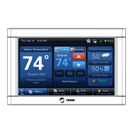
ComfortLink
™
Other Installation Guides may be necessary, based on system configuration.
A complete list of other optional components is shown below.
1 Control
Relay Panel
2
For use with 24V indoor systems
3
Zone Panel
(optional)
4
Zone Sensor with Display
5
Zone Sensor
(optional)
6
Zone Dampers
(optional)
Table of Contents
Section 1. Safety ................................................1
Section 2. General Information .........................2
Section 3. Physical Installation ........................4
Section 4. Wiring ................................................6
Section 5. System Setup ...................................9
Section 6. Advanced Features ........................15
Section 7. Troubleshooting .............................19
NOTE: See the User's Guide for
wireless setup information.
18-HD64D1-4
II Installation Guide
(optional)
(optional)
07/12
Advertisement
Table of Contents

Related Manuals for Trane 18-HD64D1-4


Summary of Contents for Trane 18-HD64D1-4
-
Page 1: Table Of Contents
18-HD64D1-4 ComfortLink ™ II Installation Guide Other Installation Guides may be necessary, based on system configuration. A complete list of other optional components is shown below. 1 Control Relay Panel For use with 24V indoor systems (optional) Zone Panel (optional) -
Page 2: Section 2. General Information
Minimum Cycle Off Time Delay: Compressor: 5 minutes, Indoor Heat: 1 minute * On every application, 24VAC loads should be reviewed to be sure the indoor unit control power transformer is adequately sized. See the Relay Panel Installer’s Guide for guidelines. 18-HD64D1-4... - Page 3 * Can alternatively be connected to the Relay Panel Outdoor Sensor** ** Can alternatively be connected to the 950 Control BAYSEN01ATEMPA * Can alternatively be connected to the Relay Panel ** Can alternatively be connected to the 950 Control 18-HD64D1-4...
-
Page 4: Section 3. Physical Installation
Gently pry the sub-base away from the Control. NOTE: This tight fit is normal and ensures that the Control is held securely to the sub-base when mounted on the wall. 18-HD64D1-4... - Page 5 #2 Phillips and insert screw. base. Screw “pops” open anchor, screwdriver or screw gun. Drive locking anchor on wall. anchor clockwise into drywall until anchor stops flush with wall. Do not overtighten screws to avoid damaging the sub-base. 18-HD64D1-4...
-
Page 6: Section 4. Wiring
Replace Control Replace unit flat onto sub-base being careful to align unit correctly with the sub-base before apply- ing force. Control should fit snug and not “rock” when prop- erly installed. Check wire routing if Control is un- stable. 18-HD64D1-4... - Page 7 Blue Blue Heat Pump Blue Blue Neatly bundle all low voltage wires behind the service valve cover as shown. Heat Pump 18-HD64D1-4 Heat Pump Control Variable Speed Neatly bundle all low voltage wires behind the service valve cover as shown.
- Page 8 Air Handler with CCM Yellow Orange Y2 - Brown Y1 - Yellow Yellow O - Orange Orange Y2 - Brown R - Red Y1 - Yellow Blue B - Blue O - Orange Brown R - Red Blue B - Blue Brown 18-HD64D1-4...
-
Page 9: Section 5. System Setup
950 Control will default to previously stored Screen Calibration settings. Note: The 950 Control is factory calibrated and can be recalibrated at any time by rebooting the Control and selecting Screen Calibration option within the five seconds following power-up. 18-HD64D1-4... -
Page 10: Available Options
Indoor Heater Minimum On Time - Min ..........1 1st Stage Indoor Heater Minimum On Time - Min......1 2nd Stage Indoor Heater Minimum On Time - Min ......1 3rd Stage Indoor Heater Minimum On Time - Min ......1 18-HD64D1-4... -
Page 11: Available Options
Control Response Rate ..............Normal Fast Aggressive Recovery > 2° Setpoint Change ........Disable Enable Heating Aggressive Recovery ............Disable Enable Heating Aggressive Recovery - Outdoor Temperature..... 0 to 70 Warm Air Discharge ................. Disable Enable 18-HD64D1-4... - Page 12 Hydronic Heat Blower Off Delay ............No Delay 30 Seconds 60 Seconds 90 Seconds Compressor Low Stage Air Flow % - Cooling ........35% - 60% 55% - 80% Compressor Low Stage Air Flow % - Compressor Heating ..... 35% - 60% 55% - 80% 18-HD64D1-4...
- Page 13 Discharge Temperature Limit - Gas Furnace Heating ...... Normal (135), Extended (145) Discharge Temperature Limit - Oil Furnace Heating ......Normal (160), Extended (170) Discharge Temperature Limit - Hydronic Heating ......Normal (135), Extended (145) Please refer to the Zone Panel Installer's Guide for detailed information. 18-HD64D1-4...
- Page 14 6) Connect wired sensor to correct Zone slot on Zone Panel. a. To re-enable the onboard temperature sensor of the 950 Control, select Zone 1, then select “Onboard Sensor” in the list of available sensors on the right-hand of screen and press “Assign” button. 18-HD64D1-4...
-
Page 15: Section 6. Advanced Features
When the control is requesting less capacity than the system can deliver, the control will duty cycle Duty Cycle to meet the required demand. The length and frequency of each duty cycle is based on the cycle rate and current load value. 18-HD64D1-4... - Page 16 The History Screen provides system cycle information. Cycle counts and run time can be viewed History Screen for first stage and second stage compressor operation, W1 & W2 heating and defrost cycles. This information can be viewed in a 24 hour, 1 week or 2 week period. 18-HD64D1-4...
- Page 17 Guest mode: The enabling of this mode allows a guest to change the temperature up to 5° in either direction from setpoint and access to the weather, but cannot change the mode or any customized settings. Note: The back door password is 9467. 18-HD64D1-4...
- Page 18 Enabling Warm Air Discharge will reduce the variable speed blower air flow by 20% when in com- Warm Air Discharge pressor heating operation. Warm air discharge only applies to compressor heating and is disabled when hydronic, fossil fuel or electrical heat (including supplement heat) modes are activated. 18-HD64D1-4...
-
Page 19: Section 7. Troubleshooting
2) Internal Control fault Follow the calibration instructions when the Control reboots. 2) Remove Control from sub base and reset. “No System Found” displayed on Internal error Reboot the Control via onscreen button. the Control 18-HD64D1-4... - Page 20 The manufacturer has a policy of continuous product and product data 6200 Troup Highway improvement and it reserves the right to change design and specifications Tyler, TX 75707 without notice. © 2012 Trane Representative-only illustrations included in this document.
Need help?
Do you have a question about the 18-HD64D1-4 and is the answer not in the manual?
Questions and answers