Table of Contents
Advertisement
11-HD12D1-2
For HVAC related
issues, contact your
servicing dealer
Contents
Features ..........................................................................................................................................................................2
Operation .........................................................................................................................................................................3
User Settings ...................................................................................................................................................................4
Scheduling .......................................................................................................................................................................5
About ...............................................................................................................................................................................9
Clean Screen ..................................................................................................................................................................9
Product Specifications ..................................................................................................................................................10
Installation and Wiring ...................................................................................................................................................10
Physical Location ..........................................................................................................................................................10
Field Wiring Diagrams ...................................................................................................................................................12
Optional Remote Temperature Sensors Installation .....................................................................................................29
Installer's Setup .............................................................................................................................................................30
Test Mode ......................................................................................................................................................................33
Restore Defaults ............................................................................................................................................................33
Troubleshooting .............................................................................................................................................................34
Limited Warranty ............................................................................................................................................................36
FCC/IC Notice ................................................................................................................................................................38
Touchscreen
Comfort Control
Model
User Guide and Installation Instructions
Î NOTE: A 24 Volt common and hot wire MUST be
connected to the CONT624A for operation.
CONT624AS42DA
........................................................................................8
1
Advertisement
Table of Contents

Related Manuals for Trane 7CONT624AS42DA


Summary of Contents for Trane 7CONT624AS42DA
-
Page 1: Table Of Contents
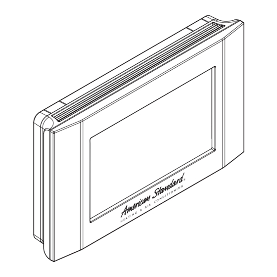
Touchscreen 11-HD12D1-2 Comfort Control Model CONT624AS42DA User Guide and Installation Instructions For HVAC related issues, contact your servicing dealer Î NOTE: A 24 Volt common and hot wire MUST be connected to the CONT624A for operation. Contents User Guide Features ..................................2 Operation ..................................3 User Settings ...................................4 Scheduling ..................................5... -
Page 2: Features
User Guide Features TCONT624AS42DA Features • 24v, Z-Wave comfort control • Remote access via smart phone, tablet, or P.C. (requires • Interactive 4.3” black & white touchscreen • 7 Day programmable, 4 schedules/day • Built in humidity sensor with RH display •... -
Page 3: Operation
User Guide Operation The model TCONT624AS42DAA Comfort Control provides typical operation of a forced air heating and cooling HVAC system. The TCONT624 comfort control also features a Z-Wave™ module for remote control. Cooling Hold Cool Auto Menu Sched Mode Normally, the Comfort Control displays the Home Screen as shown above. Item Description Notes... -
Page 4: User Settings
User Guide User Settings User Settings allow the user to customize various settings on the 624 control. To access User Settings simply press the Menu button once and “User Settings” will be displayed. To enter the User Settings menu, press the Select button, then use the Next button to navigate through the options below. -
Page 5: Scheduling
User Guide User Settings Continued User Settings allow the user to customize various settings on the 624 control. To access User Settings simply press the Menu button once and “User Settings” will be displayed. To enter the User Settings menu, press the Select button, then use the Next button to navigate through the options below. - Page 6 User Guide Scheduling Edit Schedule (Local) Press the following button sequence to edit or create an entirely new daily schedule. Edit Schedule Button Press Menu Displayed What Needs to Be Done? Press Menu from Home USER SETTINGS screen Press Next SCHEDULE Press Select EDIT SCHEDULE...
- Page 7 User Guide Scheduling Copying Schedules Press the following button sequence to access “Copying Schedules” from the Home Screen. Copying Schedules Button Press Menu Displayed What Needs to Be Done? Menu Next USER SETTINGS screen Select EDIT SCHEDULE screen Next COPY SCHEDULE screen Select COPY FROM screen (Mon) Defaults to Monday...
-
Page 8: Enrolling Into "Z-Wave" Network
User Guide Enroll Comfort Control into existing Z-Wave Network a. Power cycle the eMonitor Gateway (simple pull the plug and then plug it back in). This will leave the Gateway in inclusion mode for 3 minutes to enable you to enroll the thermostat controls. b. -
Page 9: About
About About Setting Range Version Current firmware version loaded on the control ZWAVE Ver Current version of the ZWAVE firmware Node - ID ZWAVE identification for this device Home - ID ZWAVE identification for the connected ZWAVE network Out - Type Identifies the type of outdoor unit installed C/O - Type Indicates whether the switchover valve (SOV) is energized in cooling or heating mode... -
Page 10: Installer's Guide
Installer’s Guide Product Specifications Specification Description Product Model: TCONT624AS42DAA Product: HVAC System comfort control. Z-Wave™ RF communications enabled Size: 5.75” wide x 3.5” height x 1” depth Display: Fixed Segment LCD, 4” x 2.25”, with 17 character alpha numeric display Touchscreen: Yes. - Page 11 Installer’s Guide CAUTION: ELECTRICAL HAZARD CAUTION: Before proceeding with installation, verify system power has been removed. Separate the face of the new Comfort Control from the wall plate. Apply pressure at two tabs on top of wall plate to release it. Î...
-
Page 12: Field Wiring Diagrams
Installer’s Guide Field Wiring Diagrams Heat/Cool Wiring Diagrams Heat/Cool Diagram 1: 1 or 2 Stage Cooling w/TAM7 Model Variable Speed Air Handler One or Two Stage VS Air Handler & Cooling Only Electric Heat Thermostat Connection Remote (Note 2) Sensor Outdoor Sensor (Note 3) - Page 13 Installer’s Guide Heat/Cool Wiring Diagrams Heat/Cool Diagram 3: 1 Stage Cooling w/“GAM5B” Model Air Handler One Stage Non-VS Cooling Only Air Handler & Thermostat Connection Electric Heat Remote Sensor Outdoor Sensor (Note 1) Aux relay outputs (Note 2) Remote Tempurature Sensor Connections and Operation: Notes: Sensor Options in the Installer Settings/Sensor Settings menu 1.
- Page 14 Installer’s Guide Heat/Cool Wiring Diagrams Heat/Cool Diagram 5: 1 Stage Cooling w/“GAF2-S” Model Air Handler One Stage Non-VS Cooling Only Air Handler & Thermostat Connection Electric Heat Remote Sensor Outdoor Sensor Aux relay outputs Remote Tempurature Sensor Connections and Operation: Sensor Options in the Installer Settings/Sensor Settings menu Remote Sensor (connect to the RS terminals) - None...
- Page 15 Installer’s Guide Heat/Cool Wiring Diagrams Heat/Cool Diagram 7: 1 Stage Cooling w/”GAT2” & “GAM2” Model Air Handlers One Stage Non-VS Cooling Only Air Handler & Thermostat Connection Electric Heat Remote Sensor Outdoor Sensor (Note 1) Aux relay outputs Notes: Remote Tempurature Sensor Connections and Operation: 1.
- Page 16 Outdoor Temp Sensor (connect to the ODT terminals) 3. Jumper “W2” to “W3” if three stages of indoor heat is available - None 4. For non-Trane/American Standard Indoor units “BK” is not - Outdoor connected and “Y1”/”Y2” must be connected at indoor unit.
- Page 17 2. “Y2” & “R” connections at outdoor are only required for two - None stage units - Replaces internal sensor 3. For non-Trane/American Standard Indoor units “BK” is not - Average with internal sensor connected and “Y1”/”Y2” must be connected at indoor unit. Outdoor Temp Sensor (connect to the ODT terminals)
- Page 18 Outdoor Temp Sensor (connect to the ODT terminals) stage systems - None 3. For non-Trane/American Standard Indoor units “BK” is not - Outdoor connected and “Y1”/”Y2” must be connected at indoor unit. Caution: Do not run sensor wires in the same bundle with HVAC 4.
- Page 19 1. Cut/remove the factory installed “BK” jumper on the Sensor Options in the Installer Settings/Sensor Settings menu ECM fan control board Remote Sensor (connect to the RS terminals) 2. For non-Trane/American Standard Indoor units “BK” is - None not connected - Replaces internal sensor...
- Page 20 Installer’s Guide Heat Pump Wiring Diagrams Heat Pump Diagram 1: 1 or 2 Stage Heat Pump w/TAM7 Model Variable Speed Air Handler One or Two stage Variable Speed Air Thermostat Connection Heat Pump Handler & Electric Heat Remote Sensor Outdoor Sensor (Note 2) Aux relay...
- Page 21 Installer’s Guide Heat Pump Wiring Diagrams Heat Pump Diagram 3: 1 Stage Heat Pump w/”GAM5B” Model Air Handler One stage Non-VS Air Thermostat Connection Heat Pump Handler & Electric Heat Remote Sensor Outdoor Sensor (Note 1) Aux relay outputs (Note 2) Remote Tempurature Sensor Connections and Operation: Sensor Options in the Installer Settings/Sensor Settings menu Notes:...
- Page 22 Installer’s Guide Heat Pump Wiring Diagrams Heat Pump Diagram 5: 1 Stage Heat Pump w/”GAF2-S” Model Air Handler One stage Non-VS Air Handler Thermostat Connection Heat Pump & Electric Heat Remote Sensor Outdoor Sensor Aux relay outputs Remote Tempurature Sensor Connections and Operation: Sensor Options in the Installer Settings/Sensor Settings menu Remote Sensor (connect to the RS terminals) - None...
- Page 23 Installer’s Guide Heat Pump Wiring Diagrams Heat Pump Diagram 7: 1 Stage Heat Pump w/”GAT2” & “GAM2” Model Air Handler One stage Non-VS Air Handler Thermostat Connection Heat Pump & Electric Heat Remote Sensor Outdoor Sensor (Note 1) Aux relay outputs Remote Tempurature Sensor Connections and Operation: Sensor Options in the Installer Settings/Sensor Settings menu...
- Page 24 2. Jumper “W2” to “W3” if three stages of indoor heat is available - Average with internal sensor 3. For non-Trane/American Standar indoor units “BK” is not Outdoor Temp Sensor (connect to the ODT terminals) connected and the “Y1”/”Y2” must be connected at indoor unit...
- Page 25 1. Cut/remove the factory installed “BK” jumper on the ECM fan - Replaces internal sensor control board - Average with internal sensor 2. For non-Trane/American Standard indoor units “BK” is not Outdoor Temp Sensor (connect to the ODT terminals) connected - None...
- Page 26 Sensor Options in the Installer Settings/Sensor Settings menu 1. Cut/remove the factory installed “BK” jumper at the indoor unit Remote Sensor (connect to the RS terminals) 2. For non-Trane/American Standard Indoor units “BK” is not - None connected and “Y1”/”Y2” must be connected at indoor unit.
- Page 27 - None tions - Outdoor 3. For non-Trane/American Standard indoor units “BK” is not Caution: Do not run sensor wires in the same bundle with HVAC connected and “Y1”/”Y2” must be connect at indoor unit wires. Keep away from high voltage wiring to avoid interference.
- Page 28 1. Cut/remove the factory installed “BK” jumper on the Sensor Options in the Installer Settings/Sensor Settings menu ECM fan control board Remote Sensor (connect to the RS terminals) 2. For non-Trane/American Standard Indoor units “BK” - None is not connected - Replaces internal sensor 3.
-
Page 29: Optional Remote Temperature Sensors Installation
Installer’s Guide Optional Remote Temperature Sensors Installation Wire specification for remote sensors: 2 conductors, 18 gauge wire. Make sure that the sensor wires are installed in a separate cable from the wiring to the HVAC system. Best results for distances of 100 feet or less. Accuracy may be affected for distances up to a maximum of 200 feet. -
Page 30: Installer's Setup
Installer’s Guide Installer’s Setup Installer Settings allow the user to configure the equipment settings and customize how the control operates. To access Installer Settings press the Menu button, then press Next until Service is displayed. Now press Select and hold for 5 seconds until “Installer Settings”... - Page 31 Installer’s Guide Installer’s Setup Continued Installer Settings allow the user to configure the equipment settings and customize how the control operates. To access Installer Settings press the Menu button, then press Next until “Service” is displayed. Now press Select and hold for 5 seconds until “Installer Settings”...
- Page 32 Installer’s Guide Installer’s Setup Continued Installer Settings allow the user to configure the equipment settings and customize how the control operates. To access Installer Settings press the Menu button, then press Next until “Service” is displayed. Now press Select and hold for 5 seconds until “Installer Settings”...
-
Page 33: Test Mode
Installer’s Guide Test Mode Test Mode allows the servicer to test system operation without waiting for the system to stage up/down. Also all minimum on and off times are disabled during test mode. Once a specific test has started, the test will last for 30 minutes unless the servicer ends the test by pressing the Done button. -
Page 34: Troubleshooting
Installer’s Guide Troubleshooting Troubleshooting Symptom Possible Cause Action Display will not come on Loss of 24VAC between R & C at the Control 1) Check wiring between R & C 2) Check transformer for 24VAC output 3) Check for broken or shorted thermostat wire Indoor Temperature dis- 1) Indoor temperature display needs calibrat- 1) Calibrate indoor temperature sensor... - Page 35 Base Limited Warranty Subject to the terms and conditions of this limited warranty, Trane U.S., Inc. (“Company’) extends a limited warranty against manufacturing defects for the product(s) identified in Tables 1, 1A, 1B attached hereto (“Products’) that are installed in a residential/multi-family application (personal, family or household purposes) under normal use and maintenance in the United States and Canada.
-
Page 36: Limited Warranty
Variable Speed) COVERAGE TERMS FOR RESIDENTIAL APPLICATIONS: Pursuant to the Trane U.S., Inc. (“Company”) limited warranty terms and conditions, the following Products are covered for the base time periods as stated below (“Base Limited Warranty period”). If registered, the Base Limited Warranty Periods for certain products will be extended as stated below (“Registered Limited Warranty Period”). -
Page 37: Fcc/Ic Notice
Literature Order Number 18-HD45D1-2 File number Trane 18-HD45D1-1 Supersedes 6200 Troup Highway 07/13 Date Tyler, TX 75707 www.trane.com Trane has a policy of continuous product and product data improvement and it reserves the right to change design and specifications without notice.
Need help?
Do you have a question about the 7CONT624AS42DA and is the answer not in the manual?
Questions and answers