Permobil Koala Service Manual
Hide thumbs
Also See for Koala:
- Owner's manual (60 pages) ,
- Assembly instruction manual (26 pages) ,
- Owner's manual (47 pages)
Table of Contents
Advertisement
Quick Links
Advertisement
Table of Contents

Related Manuals for Permobil Koala


Summary of Contents for Permobil Koala
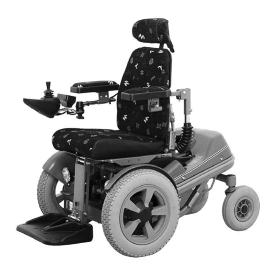
- Page 1 SERVICE MANUAL Koala...
- Page 3 Head Office of the Permobil group Permobil AB Box 120, 861 23 Timrå, Sweden Tel: +46 60 59 59 00. Fax: +46 60 57 52 50 E-mail: info@permobil.se Produced and published by Permobil AB, Sweden Edition no.5, 2006-01 Article no.: 201164-US-0...
-
Page 4: Table Of Contents
Contents Contents Introduction....................5 Technical support..................5 Spare parts ....................5 Warranties ....................5 Maintenance ..................... 5 Data Plates ....................6 Chassis ..................... 6 Pilot Motor Controller................6 Control panel .................... 6 Operating the seat elevator manually ............7 Covers......................8 Batteries ....................... -
Page 5: Introduction
Permobil to ensure that the correct information is provided. Technical Support In the event of technical problems, you should contact your dealer, or Permobil Inc. USA at 800-736-0925. Spare parts Spare parts must be ordered through your dealer. -
Page 6: Data Plates
Rating plates Data plates Chassis Fig. 1. Chassis identification number Pilot Motor Controller Fig. 2. Pilot Motor Controller identification number. Control panel Fig. 3. Control panel identification number. -
Page 7: Operating The Seat Elevator Manually
Operating the seat lift manually Operating the seat lift manually If you can not move the seat up in the normal way, because the battery is flat or there is a fault (other than in the lift mechanism), you can raise the seat by using a cable, part number 308515-00-0. -
Page 8: Covers
Covers Covers Removal 1. Raise the seat to its highest position. To operate the seat lift manually, see page 7. 2. Unscrew the two knobs that hold the front edge of the battery cover, see fig. 8. 3. Lift the battery cover at the front edge and move it backwards. -
Page 9: Batteries
Batteries Batteries Use protective goggles when working on batteries. Removal 1. Put the wheelchair on a level surface. 2. Raise the seat to its highest position. To operate the seat lift manually, see page 7. 3. Switch off the main switch on the control panel. Fig. -
Page 10: Drive Wheels
Drive wheels Drive wheels Removal 1. Switch off the main switch. 2. Lift up the chair and support it on blocks, so that the wheels are off the ground. 3. Undo and remove the hubcap (6), bolt (3) and the three washers (1 and 2), see fig. 15. 4. -
Page 11: Brake Release Cables
Brake release cables Brake release cables Removal 1. Raise the seat to its highest position. To operate the seat lift manually, see page 7. 2. Remove the battery cover and chassis cover, see page 8. 3. Remove the brake release mechanism, it is attached by two bolts, see fig. -
Page 12: Magnetic Brakes
Magnetic brake Magnetic brakes Removal 1. Put the wheelchair on a flat surface. 2. Raise the seat to its highest position. To operate the seat lift manually, see page 7. 3. Switch off the main switch on the control panel. 4. - Page 13 Magnetic brake 11. Lift up the rear end of the drive motor to make it easier to remove the magnetic brake, see fig. 22. Fig. 22. Lifting up the rear end of the motor makes the magnetic brake more accessible. 12.
- Page 14 Magnetic brake Fitting 1. Use the adjusting screws to adjust the magnetic brake. Set both screws flush with back surface of the brake, then turn the screws downwards 1/8 turn, see fig. 24. Fig. 24. Use the two adjusting screws to adjust the brake.
- Page 15 Magnetic brake 5. Fit the rubber seal, with the drainage hole at the bottom. Note the position of the brake release arm, fit the brake so that the brake release arm is aligned with motor cable mounting. Secure the magnetic brake using the three bolts. 6.
-
Page 16: Drive Motors
Drive motor Drive motor Removal 1. Raise the seat to its highest position. To operate the seat lift manually, see page 7. 2. Switch off the main switch on the control panel. 3. Put the circuit breaker to the “OFF” position, see fig. - Page 17 Drive motor 7. Remove the front battery, see page 9. 8. Raise the relevant side of the chair using the Permojack or raise the chair on blocks. 9. Remove the drive wheel on the relevant side the wheelchair, see page 10. 10.
-
Page 18: Seat Elevator
Seat lift Seat lift Actuators Removal 1. Raise the seat to its highest position. To operate the seat lift manually, see page 7. 2. Switch off the main switch on the control panel. 3. Put the circuit breaker to the “OFF” position, see page 23, fig. -
Page 19: Gas Springs
Seat lift Gas springs There are gas springs built into the parallel tubes at the sides of the seat lift. These gas springs are part of the tilt mechanism. Do not drill into the tube or gas spring, and do not expose them to heat, as this could cause an explosion. -
Page 20: Pilot Motor Controller
Pilot Motor Controller Pilot Motor Controller Removal 1. Raise the seat to its highest position. To operate the seat lift manually, see page 7. 2. Switch off the main switch on the control panel. 3. Put the circuit breaker to the “OFF” position, see page 23, fig. -
Page 21: Sls Drive Stage & Seat Function Board
SLS driver stage & Actuator control board SLS driver stage & Actuator control board The SLS driver stage and seat function board are mounted in the same box. When changing the seat function board, a new board is fitted into the existing box. -
Page 22: Control Panel
Control panel Control panel Removal Switch off the main power switch on the control panel. Put the circuit breaker in the “OFF” position, see page 23, fig. 52. Disconnect the control panel cable by pulling the connector at the rear of the control panel straight backwards. -
Page 23: Circuit Breaker And Fuses
Circuit breaker and fuses Circuit breaker and fuses Resetting the circuit breaker The circuit breaker also acts as a battery isolator, but is usually referred to as the circuit breaker. You will not normally need to change the circuit breaker, as you can reset it when it has tripped. -
Page 24: Charge Fuse
Circuit breaker and fuses Changing the charge fuse The charge fuse is on the underside of the chassis, above the right, rear wheel, beside the circuit breaker, see fig. 55. Switch off the circuit breaker and the charger, if in use, before you change the charge fuse. -
Page 25: Troubleshooting
Troubleshooting Troubleshooting Battery voltage indicator The battery voltage indicator shows the status of the wheelchair. Steady Display Everything is working correctly. Flashing slowly The batteries need to be charged. Flashing quickly Fault signal. A fault has occurred and the wheelchair can not be driven. Fault signals The number of flashing lights indicates the fault. -
Page 26: Distribution Chart
Distribution chart... -
Page 27: Distribution Chart
Distribution chart Distribution chart... - Page 28 Notes...
- Page 29 Notes...
- Page 30 Notes...
- Page 32 Article no.: 201164-US-0...
Need help?
Do you have a question about the Koala and is the answer not in the manual?
Questions and answers