Permobil M300 Owner's Manual
Hide thumbs
Also See for M300:
- User manual (206 pages) ,
- Oweners manual (164 pages) ,
- Service manual (112 pages)

Related Manuals for Permobil M300


Summary of Contents for Permobil M300
- Page 1 Owner´s Manual Permobil M300 Permobil M300 Power Wheelchair Permobil M300 Article no.: 205255-US-0...
- Page 3 Permobil Inc. USA 300 Duke Drive Lebanon, TN 37090 Phone: 800-736-0925 Fax: 800-231-3256 Email: info@permobilusa.com Head Office of the Permobil group Permobil AB Box 120 861 23 Timrå Sweden Tel: +46 60 59 59 00 Fax: +46 60 57 52 50...
- Page 4 Permobil M300 Power Wheelchair Produced and published by Permobil AB, Sweden Edition: 4, 2014-01 Order no. 205255-US-0...
-
Page 5: Table Of Contents
Owner´s Manual Permobil M300 Contents Important Information ....................6-7 Safety Instructions ....................8-23 Design and Function ....................24 General - Overview....................24 Driving - Shock absorbers ..................25 Wheels ........................26 Lights, Reflectors ....................26 Batteries - Main fuse - Charger Socket ............... 27 Seat ........................ -
Page 6: Important Information
Permobil, ask for item No. 205255-US-0. Indication for Use The intended use of the M300 series of the powered wheelchair is to provide indoor and outdoor mobility to persons limited to a seating position that are capable of operating a powered wheelchair. The M300 series of the powered... -
Page 7: Important Information
Owner´s Manual Permobil M300 Important Information TECHNICAL SUPPORT In the event of technical problems, you should contact your dealer or Permobil Inc USA at 1-800-736-0925. Always state the chassis serial number when contacting Permobil to ensure that the correct information is provided. -
Page 8: Safety Instructions
Permobil is not responsible for personal injuries or property damage resulting from any person’s failure to follow the warnings and instructions in this manual. Permobil is not responsible for injuries or damage resulting from failure to exer- cise good judgment. - Page 9 • that all products ordered are included in the delivery, incuding operating instructions and possible other documentation. If you suspect that something is missing, then contact your supplier or Permobil for more information as soon as possible. • that no transport-related or other damages have occurred to the wheelchair and its accessories.
-
Page 10: Safety Instructions
Safety Instructions m WARNING! Operation Permobil recommends the use of wheelchair lights at all times user is riding near public rights of way. Use extreme caution when driving near unprotected ledges, drop-offs or on elevated surfaces. Unintended movement or excessive speed in these areas can lead to personal injury or property damage. - Page 11 Permobil products. Weight Limitations The maximum user weight for your Permobil is set forth in the specification section of the supplied Owner´s Manual for current seat model. Operation of the wheelchair by users who exceed the maximum allowable user weight can lead to personal injury and property damage, including damage to the wheel- chair, as well as voiding any applicable warranty to the wheelchair.
- Page 12 Owner´s Manual Permobil M300 Safety Instructions Safety Instructions m CAUTION! Operation - Inclines When driving downhill, select the slowest speed and proceed with caution. Driving down an incline in a front wheel drive wheelchair can shift the user’s center of gravity forward. If the wheelchair rolls faster than you would like, stop the wheelchair by releasing the joystick and begin descending again at a slower speed.
- Page 13 Owner´s Manual Permobil M300 Safety Instructions Safety Instructions m WARNING! Operation - Inclines Do not drive the wheelchair where the sideways gradient is more than indicated in the technical specifications section of the manual. There is a risk of tipping over.
- Page 14 In order to prevent the wheelchair from rolling away, ensure that the wheelchair is on a level and dry surface before releasing the brakes. In order to avoid personal injury do not use your Permobil in freewheel mode without an attendant present. Do not attempt to put the wheelchair in freewheel mode by yourself while seated in it.
- Page 15 Driving in Extreme Climate Conditions Permobil’s wheelchairs are designed to withstand most adverse weather con- ditions, however to minimize the risk of being caught in difficult situations you should avoid using the wheelchair outdoors during, for example, severe cold, heavy rain or thick snow.
- Page 16 Owner´s Manual Permobil M300 Safety Instructions Safety Instructions m WARNING! Driving with Seat Lift/Seat Tilt/Backrest Recline Be careful in making sure that nothing gets stuck between the chassis and the seat when the seat lift/seat tilt is operated. Operating the seat lift,seat tilt/ backrest recline changes the center of gravity and increases the risk of tipping over.
- Page 17 Overextending this distance can cause user to over- exert, lose balance, or fall. Permobil recommends that users transfer in the presence of or with the assistance of an attendant. Use caution when bending or reaching.
-
Page 18: Environmental Conditions
Owner´s Manual Permobil M300 Safety Instructions Safety Instructions m WARNING! Passengers The wheelchair is not intended to transport passengers, regardless of the age of the passenger. The Maximum User Weight stated in the Owner’s Manual for your seating includes the user and any personal effects. The Maximum limit should not be exceeded. - Page 19 Use Prohibited in Motor Vehicles Permobil recommends that users NOT be transported in any kind of vehicle while in their wheelchair, unless the user is in an approved Permobil wheel- chair configuration, has secured the wheelchair using a Permolock C3, and is using a seatbelt attached to the vehicle.
- Page 20 Failure to do so can lead to personal injury. Do not use parts or accessories not authorized by Permobil. Use of unap- proved ”aftermarket” accessories and parts may cause changes in the wheel- chair, which may make the wheelchair unstable or uncontrollable.
- Page 21 Safety Instructions m WARNING! Safety Circuits Permobil products are equipped with safety circuits. Inhibit circuits prevent the wheelchair from driving under certain conditions. Speed reduction circuits limit the wheelchair’s maximum speed under certain conditions. Limit switch circuits limit the wheelchair’s functions under certain circumstances. Overload protec- tion circuits shut the wheelchair off in case of an overload.
- Page 22 Authorized Permobil service center or Permobil for more information. It’s also of greatest importance that Permobil be informed if the wheelchair and its accessories have been subjected to transport damages, damages during driving or damages due to another cause as soon as possible after the event.
-
Page 23: Safety Instructions
The limit values for Electromagnetic Compatibility (EMC) with respect to power wheelchairs is set in the harmonized standards for the EU in the Medical Devices Directive, No. 93/42/EEC. Permobil’s electronic wheelchair’s comply with these limit values. Also see Important Information about Electromagnetic Interference (EMI) on page 109-110. -
Page 24: Design And Function
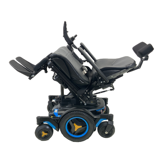
Design and Function Design & Function General The Permobil M300 is an electric mid-wheel drive wheelchair for outdoor and indoor driving. It is intended for people with physical disabilities. The wheelchair consists of a chassis and a seat. The chassis contains the wheelchair’s electronics, power supply and drive functions. -
Page 25: Driving - Shock Absorbers
Owner´s Manual Permobil M300 Design and Function Driving The Permobil M300 is equipped with a drive package for each drive wheel. The drive package consists of an electric motor with a drive gear and magnetic wheel lock. Drive gear Electric motor Wheel lock Shock absorber The wheelchair is equipped with four shock absorbers. -
Page 26: Wheels
Owner´s Manual Permobil M300 Design and Function Wheels The wheelchair’s rear wheels, the drive wheels, are available with pneumatic or Flat-Free (Foam Filled) tires. The front wheels, the caster wheels, have solid polyurethane tires. Lights and reflectors The wheelchair is equipped with reflectors on the front, rear and sides. Front/ rear lights and turn indicators are optional. -
Page 27: Batteries - Main Fuse - Charger Socket
Rear battery. Circuit Breaker The M300 is equipped with an automatic Circuit Breaker, which can be reset after having been triggered. It also functions as a battery isolator and is controlled (ON/ OFF) via the lever located inside the hole at the bottom of the rear battery cover. -
Page 28: Seat
Seat lift Permobil M300 can be fitted with an electrically controlled seat lift that allows the seat to be raised steplessly up to 8 inches in order to adjust its height to tables, benches, etc. -
Page 29: Leg Rest
Owner´s Manual Permobil M300 Design and Function Leg rest m WARNING! The following applies only if your wheelchair is equipped with separate foot plates. With the wheelchair kept still and having the leg supports driven towards it’s innermost position, the wheelchair’s front wheels must always be kept in a 90 degrees straight position, (A), pointed forward... -
Page 30: Vr2 Control Panel
Owner´s Manual Permobil M300 Design and Function (VR2) VR2 Control Panel The VR2 Control Panel consists of a joystick, function buttons and indicator lights. VR2 control panel overview Function Button Joystick Indicator Light The number of function buttons/indicator lights depends on the configuration of the wheelchair, for example, with or without lights and seatfunctions. - Page 31 Owner´s Manual Permobil M300 Design and Function (VR2) VR2 Control Panel Charger/Programming Socket This socket should only be used for charging the wheelchair. A VR2 compatible Hand-held or PC Programmer can be connected to this socket, in order to make changes to the wheelchair’s driving characteristics.
-
Page 32: Function Buttons
Owner´s Manual Permobil M300 Design and Function (VR2) VR2 Control Panel Function Buttons On the control panel there are a total of 10 Function Buttons. The number of function buttons depends on the wheelchairs configuration. On/Off Horn Button Lights Button & LED*) Hazard Button &... - Page 33 Owner´s Manual Permobil M300 Design and Function (VR2) VR2 Control Panel Power Switch, On/Off Button to power up and power down the wheelchair. This button must be pressed for the chair to operate. m WARNING! Do not use the Power Switch Button to stop the wheelchair unless there is an emergency. If you do, you may get thrown out of the chair or shorten the life of the wheelchair drive components.
- Page 34 Owner´s Manual Permobil M300 Design and Function (VR2) VR2 Control Panel Battery Charge Indicator The battery charge indicator lets you know approximately how much charge is left in your batteries(from left to right): Red+Yellow+Green = Fully charged Red+Yellow = Half charged...
- Page 35 Owner´s Manual Permobil M300 Design and Function (VR2) VR2 Control Panel Speed display Speed Indicates the adjusted speed at which the wheelchair is set. 1 - 2 lamps = Low speed 3 - 4 lamps = Medium speed 5 lamps = Maximum speed...
- Page 36 Owner´s Manual Permobil M300 Design and Function (VR2) VR2 Control Panel Locking/Unlocking the Wheelchair The wheelchair can be locked to prevent unauthorized use. Locking: • Make sure the wheelchair is turned on. Press and hold the start up button for approximately 1 sec.
- Page 37 Owner´s Manual Permobil M300 Design and Function (VR2) VR2 Control Panel Joystick The joystick is used to regulate the speed of the wheelchair forward or back- ward, to turn, and to brake. The speed is regulated proportionally by moving the joystick forward or back- ward.
-
Page 38: R-Net Control Panel Lcd Monochrome Display - Design And Function
Owner´s Manual Permobil M300 Design and Function (R-net) R-Net control panel LCD monochrome display General The Control Panel consists of a joystick, function buttons and a display. At the front of the panel is the Charger Socket. Two Jack Sockets are located on the bottom of the panel. -
Page 39: Charger Socket
Owner´s Manual Permobil M300 Design and Function (R-net) R-Net control panel LCD monochrome display Charger Socket This socket should only be used for charging or locking the wheelchair. Do not connect any type of programming cable into this socket This socket should not be used as a power supply for any other electrical device. -
Page 40: Horn Button
Owner´s Manual Permobil M300 Design and Function (R-net) R-Net control panel LCD monochrome display Function Buttons On the control panel there are a total of 10 Function Buttons. Horn Button On/Off Speedbuttons, Decrease/ PROFILE MODE Increase Profile Button Mode Lights Button & LED*) Hazard Button &... - Page 41 Owner´s Manual Permobil M300 Design and Function (R-net) R-Net control panel LCD monochrome displayl Mode Button The Mode button allows the user to navigate through the available operating Modes for the control system. The available modes are dependant on program- ming and the range of auxiliary output devices connected to the control system.
- Page 42 Owner´s Manual Permobil M300 Design and Function (R-net) R-Net control panel LCD monochrome display External On/Off Switch Jack This allows the user to turn the control system on and off using an external ability switch, such as a buddy button.
- Page 43 Owner´s Manual Permobil M300 Design and Function (R-net) R-Net control panel LCD monochrome display Display The status of the control system is shown in the display. The control system is on when the display is backlit. Screen Symbols The Drive screen for the R-net has common components, which will always appear, and components which will only appear under certain conditions.
- Page 44 Owner´s Manual Permobil M300 Design and Function (R-net) R-Net control panel LCD monochrome display Speed Indicator This displays the current speed setting. The speed setting is adjusted using the Speed Buttons. Current Profile The Profile Number describes which Profile the con- trol system is currently operating in.
- Page 45 Owner´s Manual Permobil M300 Design and Function (R-net) R-Net control panel LCD monochrome display Fault The control system can detect a wide variety of errors. When the system has detected an error that is not severe enough to cause the system to trip, then this symbol will be displayed.
-
Page 46: R-Net Control Panel Lcd Color Display - Design And Function
Owner´s Manual Permobil M300 Design and Function (R-net) R-Net control panel LCD color display General The Control Panel consists of a joystick, function buttons and a display. At the front of the panel is the Charger Socket. Two Jack Sockets are located on the bottom of the panel. - Page 47 Owner´s Manual Permobil M300 Design and Function (R-net) R-Net control panel LCD color display Charger Socket This socket should only be used for charging or locking the wheelchair. Do not connect any type of programming cable into this socket This socket should not be used as a power supply for any other electrical device.
- Page 48 Owner´s Manual Permobil M300 Design and Function (R-net) R-Net control panel LCD color display Function Buttons On the control panel there are a total of 10 Function Buttons. Horn Button On/Off Speedbuttons, Decrease/ PROFILE MODE Increase Profile Button Mode Lights Button & LED*) Hazard Button &...
- Page 49 Owner´s Manual Permobil M300 Design and Function (R-net) R-Net control panel LCD color display Mode Button The Mode button allows the user to navigate through the available operating Modes for the control system. The available modes are dependant on program- ming and the range of auxiliary output devices connected to the control system.
- Page 50 Owner´s Manual Permobil M300 Design and Function (R-net) R-Net control panel LCD color display External On/Off Switch Jack This allows the user to turn the control system on and off using an external ability switch, such as a buddy button.
- Page 51 Owner´s Manual Permobil M300 Design and Function (R-net) R-Net control panel LCD color display Display The status of the control system is shown in the display. The control system is on when the display is backlit. Screen Symbols The Drive screen for the R-net has common components, which will always appear, and components which will only appear under certain conditions.
- Page 52 Owner´s Manual Permobil M300 Design and Function (R-net) R-Net control panel LCD color display Speed Indicator This displays the current speed setting. The speed setting is adjusted using the Speed Buttons. Current Profile The Profile Number describes which Profile the con- trol system is currently operating in.
- Page 53 Owner´s Manual Permobil M300 Design and Function (R-net) R-Net control panel LCD color display Motor Temperature This symbol is displayed when the control system has intentionally reduced the power to the motors, in order to protect them against heat damage.
-
Page 54: Installation Menu
Owner´s Manual Permobil M300 Design and Function (R-net) R-Net control panel LCD color display Installation menu The installation menu permits the user to set the clock, the display brightness, background color etc. Access the menu by holding down the keys for higher and lower maximum speed simultaneously. - Page 55 Owner´s Manual Permobil M300 Design and Function (R-net) Control panel R-Net LCD color display Distance measurement (Distance) Select “Distance” in the menu. Move the joystick to the right to go to the menu for setting distance measurement. Then select “Total distance”, “Trip”, “Distance display”...
-
Page 56: R-Net Control Panel Led - Design And Function
Owner´s Manual Permobil M300 Design and Function (R-net) R-Net control panel LED General The Control Panel consists of a joystick, function buttons and a display. At the front of the panel is the Charger Socket. Two Jack Sockets are located on the bottom of the panel. - Page 57 Owner´s Manual Permobil M300 Design and Function (R-net) R-Net control panel LED Charger Socket This socket should only be used for charging or locking the wheelchair. Do not connect any type of programming cable into this socket This socket should not be used as a power supply for any other electrical device.
- Page 58 Owner´s Manual Permobil M300 Design and Function (R-net) R-Net control panel LED Function keys There are a total of 9 function keys on the control panel with LEDs. Horn Battery voltage indicator On/Off Mode Seat indicator Max. speed/profile Lights* Hazard lights* indicator Max.
- Page 59 Owner´s Manual Permobil M300 Design and Function (R-net) R-Net control panel LED Mode With the Mode key the user can scroll between the control system’s available operating modes. The available modes depend on the programming and on which other output devices are connected to the control system.
- Page 60 Owner´s Manual Permobil M300 Design and Function (R-net) R-Net control panel LED Battery voltage indicator Shows the voltage remaining in the batteries (from left to right): Red+Yellow+Green = Fully charged Red+Yellow = Half charged = Charge the batteries A good way of using this indicator is to learn how it works while you are driv- ing.
- Page 61 Owner´s Manual Permobil M300 Design and Function (R-net) R-Net control panel LED Max. speed indicator Speed Indicates the maximum speed set for the wheelchair. 2 lamps = Low speed 4 lamps = Average speed 5 lamps = Max. speed Driving profile For special applications, the wheelchair can be programmed with more than one driving profile.
- Page 62 Owner´s Manual Permobil M300 Design and Function (R-net) R-Net control panel LED Seat indicator On certain seats the electrical functions for seat lift, seat angle, backrest angle and legrest angle are controlled with the control panel joystick. In this case the active seat function is indicated on the control panel seat indicator.
-
Page 63: Handling
Handling Handling General The Permobil M300 is designed for indoor and outdoor use. When driving indoors, you must observe care when driving in, for example, narrow passageways, when passing through doors and entries, as well as, when using elevators, ramps, etc. -
Page 64: General - Driving
Owner´s Manual Permobil M300 Handling Driving - General Make sure that the control system is mounted securely and that the joystick position is correct. The body part that you use to operate the joystick should be supported, for example by the wheelchair arm pad. Do not use the joystick as the sole support for your hand or limb - wheelchair movements and bumps could upset your control. -
Page 65: Joystick Error - Vr2
Owner´s Manual Permobil M300 Handling Joystick Error - VR2 Control System If the joystick is pushed before or just after the control system is turned on, the battery indicator will ripple up and down and the wheelchair will not be allowed to move. -
Page 66: Joystick Error - R-Net
Owner´s Manual Permobil M300 Design and Function (R-net) Joystick Error - R-Net Control System If the joystick is moved from the central position before, during or immediately after the control system is switched on, the screen image for a shifted joystick will be displayed for 5 seconds. -
Page 67: Driving Technique
Owner´s Manual Permobil M300 Design and Function (R-net) Driving Technique The control system electronics “interpret” the movements of the joystick and move the wheelchair as intended. For normal driving, the user doesn’t need to employ any complex techniques, which is an advantage if the user is inexperienced. A good way of starting is quite simply to move the joystick in the direction you want to go. - Page 68 Owner´s Manual Permobil M300 Handling R-Net control panel Locking/unlocking the wheelchair The control system can be locked in two different ways. Either by using a key sequence on the keypad or with a physical key. The method used depends on how the system has been programmed.
- Page 69 Owner´s Manual Permobil M300 Handling R-Net control panel Locking with a key • Press the on/off key if the control system is switched off. • Insert and remove the key from the charging contact on the control panel. • The wheelchair is now locked.
-
Page 70: Seat Functions
Owner´s Manual Permobil M300 Handling Seat functions - R-net electronics (Not applicable to all seat models) On some seats the electrical functions can be controlled with the help of the control panel joystick. Some models are equipped with three memory locations. - Page 71 Owner´s Manual Permobil M300 Handling Seat functions - R-net electronics (Not applicable to all seat models) Return to drive mode Press the “Mode” button one or more times until a standard display image with speed indicator appears in the control panel display - see illustration.
- Page 72 Owner´s Manual Permobil M300 Handling Seat functions - R-net electronics (Not applicable to all seat models) The control system on some seats has three memory locations for seat pos- itions. Each memory location can store the position of the seat’s adjustment device.
- Page 73 Owner´s Manual Permobil M300 Handling Seat functions - R-net electronics (Not applicable to all seat models) Saving position to memory 1. Set the seat’s electrical functions to the desired mode. 2. If not activated, activate the seat/ memory function by pressing the “Mode”...
- Page 74 Owner´s Manual Permobil M300 Handling Seat functions R-Net LED (Not applicable to all seat models) On certain seats the electrical functions for seat lift, seat angle, backrest angle and legrest angle are controlled with the control panel joystick. Other seat functions require a separate seat con- trol panel.
- Page 75 Owner´s Manual Permobil M300 Handling Seat functions R-Net LED (Not applicable to all seat models) Return to drive mode Press the “Mode” button one or more times until a standard display image with speed indicator appears in the control panel display - see illustration.
-
Page 76: Driving Rules
Owner´s Manual Permobil M300 Handling Driving Rules m WARNING! Always bear in mind that high speed and extended braking distance entail an increased risk of accidents. Never drive rapidly or at full speed along narrow passages, on narrow sidewalks, etc. where an incorrect maneuver or incorrect steering can cause an increased risk of accidents. -
Page 77: Driving Over Obstacles
Owner´s Manual Permobil M300 Handling Driving Rules Driving over Obstacles Do not drive the wheelchair over obstacles of a height greater than 3 inches. Driving over tall edges increases the risk of tipping over as well as the risk of damage to the wheelchair. - Page 78 Owner´s Manual Permobil M300 Handling Driving downhill You should always drive downhill at low speed and with great caution. Avoid braking suddenly and sudden evasive maneuvers and never drive so fast that you are unable to control the wheelchair safely without risks.
- Page 79 Owner´s Manual Permobil M300 Handling Driving uphill You should always drive uphill with great caution. Avoid sudden evasive maneuvers and never drive so fast that you are unable to control the wheelchair safely without risks. Safe slope 8° m WARNING! Do not drive uphill on a gradient greater than 8°.
- Page 80 Owner´s Manual Permobil M300 Handling Driving on Sideways Slopes Driving on a sideways slope must always be performed with great care. Avoid abrupt avoidance maneuvers and never maintain a speed higher than that at which you can maneuver the wheelchair in a safe and secure manner.
-
Page 81: Manual Release Of The Magnetic Wheel Locks
Always reset the wheel lock release after manually moving the wheelchair. m CAUTION! When the wheel locks are released, the chair Wheel lock engaged. will not drive. If it does, contact an Authorized Permobil service center as soon as possible. -
Page 82: Battery Charging
Owner´s Manual Permobil M300 Handling Battery Charging The amount of charge in your batteries depends on a number of factors, includ- ing the way you use your wheelchair, the temperature of the batteries, their age and the way they are made. These factors will affect the distance you can travel in your wheelchair between charging the batteries. -
Page 83: Charging
Ensure that the charger plug is pushed fully into position before turning on the battery charger. You will not be able to drive the wheelchair when the charger is connected. If the wheelchair does drive with the charger plugged in, contact an Authorized Permobil service center as soon as possible. m WARNING! Only use the battery charger that has been supplied with your wheelchair or recommended by Permobil. -
Page 84: Transport
WARNING! Use Prohibited in Motor Vehicles Permobil recommends that users NOT be transported in any kind of vehicle while in their wheel- chair, unless the user is in an approved Permobil wheelchair configuration, has secured the wheel- chair using a Permolock C3, and is using a seatbelt attached to the vehicle. The only other safe alternative is that users be transferred into factory vehicle seating for transportation and use safety restraints made available by the auto industry. - Page 85 Owner´s Manual Permobil M300 Transport m WARNING! If the wheelchair has to be transported with the user in the chair into the vehicle through a ramp, the wheelchair shall be secured against tipping backwards by a person behind. Wheelchair users should transfer to the vehicle seat and use the vehicle-installed restraint system whenever it is feasible.
-
Page 86: General Advice For Air Transport
Owner´s Manual Permobil M300 Transport General Advice for Air transport Please refer to the Air Carrier Access Act at 49 USC § 41705 and accompanying regulations at 14 CFR Part 382 for specific guidelines and regulations pertaining to transporting wheelchairs on aircraft in the United States. - Page 87 Owner´s Manual Permobil M300 Transport General Advice for Air transport 3. Preventing Damages The electronic components, as well as other critical parts, in your wheelchair are highly sophisticated and fragile and care must be taken to protect them. When transporting your wheelchair by air, we recommend that you cover the control panel with soft, shock-absorbing material (foamed plastic or similar) and fold it in towards the center of the seat.
-
Page 88: Maintenance And Repairs
Owner´s Manual Permobil M300 Maintenance and Repairs Maintenance and Repairs To ensure that your wheelchair works well, you must inspect, maintain, and obtain routine service on it regularly. Every wheelchair is subject to wear and tear between the moving parts and also due to the strains and stresses of typical use. -
Page 89: General Batteries/Storage
Owner´s Manual Permobil M300 Maintenance and Repairs General Batteries/Storage • Note that a battery drains on its own and a discharged battery can freeze and burst when it is cold. If the wheelchair must be stored without being used for a long period of time, the batteries should always be charged up once per month so that they do not incur any damage. -
Page 90: Finishes Care And Maintenance
Owner´s Manual Permobil M300 Maintenance and Repairs Maintenance and Repairs With regular care and maintenance, your Permobil will provide years of superior performance and satisfaction. To maintain the finish quality of your wheelchair, please follow the cleaning procedures provided below. - Page 91 Owner´s Manual Permobil M300 Maintenance and Repairs Maintenance and Repairs Wheel Lock Release Check regularly, approximately once per month, the functionality of the wheel lock release. It must not be possible to drive the wheelchair when the wheel locks are disengaged.
- Page 92 Owner´s Manual Permobil M300 Maintenance and Repairs Maintenance and Repairs Changing inner tube 1. Switch off the main power switch on the control panel. 2. Lift up and chock up the wheel- chair chassis so that the wheel in question is free of the ground.
-
Page 93: Tire Pressure
Owner´s Manual Permobil M300 Maintenance and Repairs Maintenance and Repairs Tire pressure Check at regular intervals that the wheelchair’s tires have the prescribed tire pres- sure. An incorrect tire pressure can cause deterioration in stability and manuever- ability, plus extremely low air pressure can give rise to abnormal wear as well as shorter driving distances. -
Page 94: Changing The Batteries
Owner´s Manual Permobil M300 Maintenance and Repairs Changing the batteries Front battery 1. Place the wheelchair on a level surface. 2. Run/fold out the leg support and raise the seat lift. 3. Turn off the main power switch on the control panel. - Page 95 Owner´s Manual Permobil M300 Maintenance and Repairs Changing the batteries Front battery 6. Loosen the battery locks. See figure. 7. Loosen the battery terminals, see figure. below. Also see the sticker on the inside of the chassis front cover. 8. Lift/pull the battery out using the battery strap.
- Page 96 Owner´s Manual Permobil M300 Maintenance and Repairs Changing the batteries Rear battery 1. Place the wheelchair on a level surface. 2. Run/fold out the leg support and raise the seat lift. 3. Turn off the main power switch on the control panel.
- Page 97 Owner´s Manual Permobil M300 Maintenance and Repairs Changing the batteries Rear battery 8. Remove the electronics by pulling the release lips on the left and right hand side of the chassis outwards. See fig. 9. Loosen the battery locks. See fig.
-
Page 98: Resetting The Circuit Breaker
WARNING! A triggered automatic Circuit Breaker can indicate larger electrical faults. The cause should be checked carefully before the Circuit Breaker is reset. Always contact an authorized Permobil Service Center or Permobil when in doubt. The circuit breaker also serves as a battery isolator, but is normally referred to as a circuit breaker. -
Page 99: Accessories
Owner´s Manual Permobil M300 Accessories Accessories We are constantly developing accessories for our wheelchairs. Contact your nearest Permobil retailer for more information about the accessories available for your wheelchair. -
Page 100: Technical Specifications
Owner´s Manual Permobil M300 Technical Specifications Technical Specifications The specifications given in the following pages are only applicable to the Permobil M300 chassis with Corpus 3G. For size and weight information about each seat, see the Owner’s Manual accompanying the seat. Length 41”... - Page 101 Owner´s Manual Permobil M300 Technical Specifications DATA General name ................Permobil M300 Size and weight length ................41” width ................24” Height ................46” smallest Transport size, lxwxh ........31”x24”x32” weight incl. Batteries and Corpus 3G seat ....345lbs Max. Battery size ............10.2x6.6x7”...
-
Page 102: Troubleshooting Guide
The remedying of errors that are indicated via the control panel display must be performed by a qualified service technician authorized by Permobil to perform such service on Permobil products. Permobil Inc. is not responsible for personal injuries or damage resulting from inappropriate or wrongly performed repairs. -
Page 103: Error Codes
Owner´s Manual Permobil M300 Troubleshooting Guide ERROR CODE POSSIBLE CAUSE - SOLUTION 1 LED - Low battery voltage Check the battery and the connections between the battery and the control unit. 2 LED - Open circuit, left drive motor Check the connection to the right drive motor. -
Page 104: Diagnostic Screens
The remedying of errors that are indicated via the control panel display must be performed by a qualified service technician authorized by Permobil to perform such service on Permobil products. Permobil Inc. is not responsible for personal injuries or damage resulting from inappropriate or wrongly performed repairs. - Page 105 CAUTION! Any replacement work carried out without Permobil’s permission will invalidate the control system’s warranty. Permobil accepts no liability for losses of any kind arising from unauthorized opening, adjustments or modifications to any component of the R-net control system.
- Page 106 Incorrect or poorly performed repair work may make it dangerous to use the wheelchair. Permobil accepts no liability for any personal injury or damage to the wheelchair and its surroundings that may occur on account of incorrect or poorly performed repair work.
- Page 107 Owner´s Manual Permobil M300 Troubleshooting Guide ERROR SIGNAL ERROR INDICATION - REMEDY 1 Lamp - Low battery voltage Check the condition of the battery. Check the contact between the battery and the control unit. 2 Lamps - Failure in left-hand drive motor Check the connection to the left-hand drive motor.
- Page 108 Note that this guide does not describe all the possible events that can arise, and you should always get in touch with your service contact or Permobil when you are unsure...
-
Page 109: Important Information About Electromagnetic Interference (Emi)
Owner´s Manual Permobil M300 Electromagnetic Interference m WARNING! It is very important that you read this information regarding the possible effects of Electromagnetic Interference on your powered wheelchair. Electromagnetic Interference (EMI) From Radio Wave Sources Powered wheelchairs and motorized scooters (in this text, both will be referred... - Page 110 Owner´s Manual Permobil M300 Electromagnetic Interference CAUTION! Other types of hand-held devices, such as cordless phones, laptop computers, AM/FM radios, TV sets, CD players, and casette players, and small appliances, such as electric shavers and hair dryers, so far we know, are not likely to cause EMI problems to your powered wheelchair.
Need help?
Do you have a question about the M300 and is the answer not in the manual?
Questions and answers
Battery are dead is there a way to manually put the seat up to take the battery out
To manually raise the seat on a Permobil M300 to remove the dead battery:
1. Use the seat lift crank to manually raise the seat.
2. If the wheelchair has a fixed seat post or the seat lift isn't working due to dead batteries or a fault, manual raising/lowering is still possible.
3. Raise the seat to the highest position.
This allows access to remove the seat and reach the batteries.
This answer is automatically generated
Ok thanks just don't see a crank is it a bolt that u have to use allen wrench to crank it
The rear wheel spending but don't grip
The rear wheel of the Permobil M300 may be spinning but not gripping due to being in freewheel mode. In this mode, the motors are disengaged, allowing the wheels to spin freely. This can happen if the freewheel levers are released, especially while on an incline or uneven surface. Always ensure the wheelchair is not in freewheel mode unless necessary and attended.
This answer is automatically generated
what is module error 1802 it is a permobile M300 wheel chair