GE JP938 Technical Service Manual
Electronic touch control & electric manual control cooktops
Hide thumbs
Also See for JP938:
- Product information (2 pages) ,
- Owner's manual (40 pages) ,
- Installation instructions manual (17 pages)

Related Manuals for GE JP938


Summary of Contents for GE JP938
- Page 1 GE Consumer Home Services Training TECHNICAL SERVICE GUIDE Electronic Touch Control & Electric Manual Control Cooktops MODEL SERIES: Electronic: JP938 JP968 Electric: JP340 JP350 JP930 JP960 PUB # 31-9070 01/01...
- Page 2 If grounding wires, screws, straps, clips, nuts, or washers used to complete a path to ground are removed for service, they must be returned to their original position and properly fastened. GE Consumer Home Services Training Technical Service Guide Copyright © 2000 All rights reserved.
-
Page 3: Table Of Contents
Table of Contents Table of Contents Introduction ........... . . 2 Installation . -
Page 4: Introduction
OFF after 60 seconds of removing It’s easy to see how GE’s fresh ideas can make a metallic pan from the heater. The pan sizing anyone more creative in the kitchen! -
Page 5: Installation
4-5/8" on models JP960/930/350/340. GEA00792 36-in. and 30-in. Cooktops Refer to installation instructions. Installation cooktops are approved for use over select GE requires an 18-in. minimum distance from 27-in. and GE 30-in. single wall ovens. cooktop to adjacent overhead cabinets. Units are Note: If installing with a GE Profile Performance™... - Page 6 Grounding Specifications for a counter-mounted cooktop and not more than two wall-mounted ovens – all supplied from Ground Path Resistance 0.10 ohms Max. a single branch circuit and located in the same Insulation Resistance 250K ohms Min. room – shall be computed by adding the name- plate ratings on the individual appliances and treating this total as equivalent to one range.
-
Page 7: Specifications And
For specifications table, refer to Cooktop Features and Controls, page 11. Model Number J P 9 6 8 B C Product Grate Type J = GE Cooking Product C = Continuous Configuration Glass Color P = Cooktop B = Black glass Feature Pack Designates features–the higher... -
Page 8: Warranty Information
Any part of the cooktop that fails due to a defect in materials or workman- From the date of the ship. During this full one-year warranty, GE will also provide, free of charge, all labor and in-home service to replace the defective part. -
Page 9: Cooktop Features And Controls
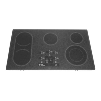
4. Pan Sizing* 5. Control Lock-out* 6. Kitchen Timer* 7. Ribbon-Type Heating Elements 8. 7-in. Heating/Warming Element* *Some Models, JP938 & JP968 JP930 (30-in.) Electric Cooktop JP938 (30-in.) Electronic Cooktop Ceramic Glass Surface These cooktops feature a ceramic glass cooking Before replacing the cooktop, try using the surface over an electric radiant surface element. -
Page 10: Bridge Element
Heating Element Systems Bridge Element The Bridge Element is made up of two 7-in., The Haliant Surface Element consists of a ribbon- 1800 watt elements plus an 800 watt element type resistance wire attached to the support insula- between the two 7-in. elements. The elements tion with molded ceramic fiber walls in a corrosion- protected metal dish. - Page 11 Electronic Touch Controls (Some Models, JP938 & JP968) The touch controls provide precise control of the surface elements. You can quickly switch from a steady low heat to full power or any setting in between. To turn ON the bridge element, set the left front surface element to the desired setting.
- Page 12 Indicator Lights TROL LOCK pad again for 3 seconds. A 2-beep signal will sound and the light will go Lights will come ON next to the bridge, warmer, out, indicating the cooktop is unlocked. dual unit, or control lockout pads when touched, Locking the cooktop will prevent surface to indicate the surface element or feature is elements from accidentally being energized by...
-
Page 13: Pan Sizing
Built-In CleanDesign Cooktops GE Profile Performance Series GE Profile ™ ™ Ribbon Ribbon Ribbon JP350SC JP968SC JP960SC JP938SC JP930SC JP350TC JP968WC JP960TC JP938WC JP930TC JP350WC JP340WC JP968CC JP960CC JP938CC JP930CC JP350CC JP968BC JP960BC JP938BC JP930BC JP350BC JP340BC Features Patterned Black... -
Page 14: Diagnostics
Diagnostics Table of Contents Digital Control System ..........13 Triac Voltage Control . -
Page 15: Digital Control System
Digital Control System • If the touch board is damaged, the entire glass The control system consists of four circuit boards: assembly must be replaced. the touch board (which is permanently adhered to the ceramic glass panel) that senses the user •... -
Page 16: Pan Detection
Pan Detection Technician Mode The pan detection system includes a pan sensor, To enter the Technician Mode, lock the cooktop by an inductive sensor interface chip (ISIC) perma- holding the CONTROL LOCK key for 3 seconds. nently mounted on the logic board, and a signal wiring harness connecting the sensor with the ISIC. -
Page 17: Fault Codes (F-Codes)
Fault Codes (F-codes) To clear the F-code register, enter Technician Mode. While the timer display flashes TECH When a fault code (F-code) occurs, an alarm will MODE, simultaneously press the BRIDGE and sound for 1 minute, the F-code will flash in the WARMER keys. -
Page 18: Frequency Check (In Hertz)
Frequency Check (in Hertz) To check the frequency of a specific pan sensor, press the (-) key of that element while in Techni- cian Mode. H will display in the window of the specific surface element. The frequency will appear in the timer display. Calibration of the Inductive Pan Sensors Calibration of the inductive sensors is performed to permanently store the pan detection thresholds... -
Page 19: Fault Code Behavior Table
Fault Code Behavior Table – 17 –... -
Page 20: Mechanical Disassembly
Mechanical Disassembly Table of Contents Nonelectronic Models ..........19 Glass and Cooktop Removal from Countertop . -
Page 21: Nonelectronic Models
NONELECTRONIC MODELS Remove these screws WARNING: Before servicing the cooktop, power must be removed from the cooktop by pulling the plug out of the outlet or turning the power off at the circuit breaker. Glass and Cooktop Removal from 6. Remove all screws from along the top edge on Countertop all 4 sides of the burner box. -
Page 22: Hot Surface Light Replacement
2. Remove 4 screws from the switch mounting bracket (2 from each end). 3. Remove 2 screws and the switch from the mounting bracket. 4. Tag and remove the wires from the switch. HOT SURFACE Light Replacement LR Burner Switch LR Burner Switch 1. -
Page 23: Electronic Models
ELECTRONIC MODELS WARNING: Before servicing the cooktop, power must be removed from the cooktop by pulling the plug out of the outlet or turning the power off at the circuit breaker. Glass and Cooktop Removal from Countertop Note: The ceramic glass and touch board shall be supplied as a complete assembly. -
Page 24: Touch Board And Cooktop Glass Replacement
6. With the glass tilted at an angle, disconnect the 3. Prop the glass on the back of the cooktop. wire harness that extends from the logic board Using one hand to lower the glass, use the to the user interface by pulling upward on the other hand to connect the wire harness from the connector. -
Page 25: Power Board Replacement
Press Down on Latching Tabs Press Down on Latching Tabs 26-Pin 26-Pin 10-Pin 10-Pin Ribbon Cable Ribbon Cable Header Header GEA00848 GEA00823 8. Prop the glass onto the back of the cooktop. Using one hand to lower the glass, use the 3. -
Page 26: Calibration Instructions For The Inductive Sensors
3. Remove 5 screws and the ground screw from the drop box cover and lower the cover. Main Power Connector Main Power Connector Main Power Connector 9. Prop the glass onto the back of the cooktop. 26-Pin Cable 26-Pin Cable 26-Pin Cable Using one hand to lower the glass, use the other hand to connect the wire harness from... -
Page 27: Surface Element Replacement
5. When the TIMER window displays DISC and the U symbol stops flashing in the LF surface element power window, center the aluminum disk on the LF surface element. 6. Press the PAN and LF (+) keys at the same time. - Page 28 Using a nut driver, remove the necessary screws from the outside of the burner box and lift the surface element support bracket to route the sensor wires beneath the bracket. Remove the electrical connectors form the heater. 5. Lift the heater off the springs and mark the numbers on the bottom of the heater next to the tabs.
-
Page 29: Component And Connector Locator Views
Component and Connector Locator Views JP968 (36-in.) Electronic Cooktop 26-Pin Ribbon 26-Pin Ribbon Main Power Main Power Ceramic Glass Top Ceramic Glass Top Connector Connector Connector Connector Display Board Display Board Touch Board Touch Board Power Board Power Board Ceramic Ceramic Glass Top Glass Top... - Page 30 JP938 (30-in.) Electronic Cooktop 26-Pin Ribbon 26-Pin Ribbon Main Power Main Power Ceramic Ceramic User Interface to Logic User Interface to Logic Connector Connector Connector Connector Glass Top Glass Top Board Wire Harness Board Wire Harness Power Power Board Board...
- Page 31 JP350 (30-in.) Electric Cooktop Heater Heater Thermal Limiter Thermal Limiter Switch Switch Switch Switch Mounting Mounting Bracket Bracket Burner Box Burner Box HOT SURFACE HOT SURFACE HOT SURFACE Support Support ON Light ON Light Lights Lights Bracket Bracket GEA00838 – 29 –...
-
Page 32: Schematics
BRIDGE JP968 MODEL ONL Y INDUCTIVE SENSOR WIRE 1800W 800W 1800W 1500W 1500W 1200W 1000W Blue with Black J502 Traces J504 J501 CONNECTOR J503 Blue Yellow with Inductive traces RTD Wire Sensor (jumper wire) Example: J505 Empty Pin 9-PIN POWER CONNECTOR (Pin 5) (Pin 1) - Page 33 Notes – 31 –...
-
Page 34: Parts List
Parts List – 32 –... - Page 35 Ref No. Part No. Description Qty. WB27T10293 Logic Board WB27T10294 Display Board WB02T10092 Burner Box Grommet WB62T10088 Glass Maintop Asm 36” WB02K5328 Hold Down Bracket WB30T10066 Element Radiant Asm WB30T10067 Element Radiant Asm WB30T10065 Element Radiant Asm WB30T10062 Element Radiant Asm WB09K5014 Radiant Spring WB64T10021...
- Page 36 – 34 –...
- Page 37 Ref No. Part No. Description Qty. WB01X1424 Screw WH02X0930 Screw 8-18 AB HXW 3/8 WB01K5117 Washer .250IDX.8120D WB01X1260 Ground Washer WB02T10093 Standoff PCB 49-80021 Use & Care Manual WB18T10162 Power Control Harness WB18T10163 Heater Control Harness WB18T10164 Logic Control Harness WB18T10166 Logic Display Harness WB18T10165...
Need help?
Do you have a question about the JP938 and is the answer not in the manual?
Questions and answers
REMOVED SCREWS AROUND GLASSTOP BUT CANNOT LIFT IT OFF
After removing all screws from along the top edge on all four sides of the burner box, remove the cooktop glass and place it top side down on a protected surface.
This answer is automatically generated