
Related Manuals for Hubbell J


Summary of Contents for Hubbell J
- Page 1 OPERATING AND MAINTENANCE MANUAL FOR ELECTRIC BOOSTER HEATER ELECTRIC HEATER COMPANY BASE MODEL “ J ” ASME ANSI/NSF5 2010 Edition...
- Page 2 9. This water heater is not intended for space heating applications. 10. The water heater is factory set at 185°F for booster water heating applications. This results in the possibility of a scalding water injury. A full thickness skin burn can occur in less than one second of exposure to water at this temperature.
- Page 3 SECTION TITLE GENERAL DESCRIPTION AND CONSTRUCTION INSTALLATION AND START-UP SCHEDULED MAINTENANCE AND OPERATION TROUBLESHOOTING SERVICING AND REPLACEMENT OF PARTS SERVICE PARTS LIST TORQUE VALUES VIII WARRANTY INFORMATION TABLE OF CONTENTS PAGE No.
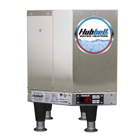
- Page 4 SECTION I - GENERAL DESCRIPTION This book describes a packaged electric booster heater that is typically used to provide 180°F sanitizing rinse water. The complete assembly consists of the storage tank, immersion electric heating element(s), electronic control module, safety relief valve, magnetic contactor(s), and any other required electrical operating control.
- Page 7 See drawing for locations and sizes. HEATING ELEMENT The water heater is supplied with an electric immersion heating element assembly(s), composed of copper sheathed elements that are fitted into a brass 1½-12UNF screw plug with 1-7/8”...
- Page 8 PRESSURE REDUCING VALVE A bronze pressure reducing valve with built-in bypass is supplied with the unit. This valve is shipped separately for in-line installation. The ¾” NPT valve is adjustable from 25-psi to 75-psi. The inlet connection is supplied with a ¾”...
- Page 9 1. Place the heater on a solid, level foundation in a clean, dry location as near as possible to the dish washing machine. 2. The water heater should be protected from freezing and waterlines insulated to reduce energy and water waste.
- Page 10 2. Attach slide bracket angles to heater with #8 sheet metal screws. It will be necessary to drill 1/8” holes into heater jacket for screw pilot holes. 3. Slide heater onto slide rails under dishtable. PIPING INSTALLATION – See Diagrams NOTES: •...
- Page 11 c. Maximum four (4) elbows d. No reduction in line size e. No valve of any type to be installed between the relief valve and tank or in the drain line f. Termination to be 6-inches above the drain 7. A shock absorber is recommended in the hot water outlet line to soften the water hammer caused by automatic dishwasher solenoid valves.
- Page 12 3. To set the XB1 setpoint, turn the potentiometer clockwise for a higher setpoint and counter-clockwise for a lower setpoint. The range is adjustable between 150°F and 180°F. 4. Make connections as required to the relay terminal block. When the temperature drops below the XB1 setpoint the relay is open between Normally Open (NO) and Common (C) and the LED will flash green.
- Page 13 OPTIONAL FIELD CONVERSION FROM SINGLE TO THREE PHASE OR THREE TO SINGLE PHASE (J6 and J16 models in 6, 7, and 9 kW and 208 and 240 volts and J411 models only) 1. For J6 and J16 models: a. Find the appropriate diagram for the unit to be converted in the following chart titled “Wiring Chart”.
- Page 14 Unit Branch Volt Ph Draw Draw 12.5 16.7 25.0 19.2 16.7 10.7 24.0 20.8 13.2 10.4 28.8 16.7 25.0 14.4 32.5 18.7 30.5 17.6 10.0 43.3 25.0 37.5 21.7 14.3 10.8 48.8 29.1 43.8 10.5 25.3 17.1 12.6 10.2 57.7 33.3 50.0 28.9...
- Page 15 Unit Branch Volt Ph Draw Draw 72.1 72.1 41.6 41.6 62.5 62.5 36.1 36.1 22.9 22.9 18.0 18.0 14.7 14.7 86.5 86.5 50.0 50.0 75.0 75.0 43.3 43.3 27.9 27.9 21.7 21.7 18.1 18.1 115.4 38.5 66.6 66.6 100.0 33.3 57.7 57.7 37.1...
- Page 16 Unit Branch kW Volt Ph Draw Draw 195.0 65.0 112.6 56.3 168.8 56.3 40.5 97.4 48.7 60.8 60.8 48.7 48.7 36.2 36.2 119.1 59.5 187.5 62.5 108.3 54.1 68.6 34.3 54.1 54.1 42.2 42.2 149.9 74.9 129.9 65.0 80.0 40.0 65.0 65.0 54.3...
- Page 17 Unit Volt Draw 23.8 47.5 47.6 27.5 51.9 10.4 28.8 47.5 27.4 41.2 11.4 16.8 15.9 13.7 11.0 J3 Wiring Chart Notes: 1. Power feed wire sizing is based on using 75°C Cu THHN wire with feeder branch protection rated at 125%. 2.
- Page 18 Note: Wiring diagrams 3, 5, 6, 7 (NT), 7 (WT), and 11 are obsolete. 1(WT) Control, Low Water, & Hi-Limit Probe 10(WT) Control, Low Water, & Hi-Limit Probe 1(NT) Control, Low Water, Control Module & Display Leak Detection Probe 10(NT) Control Module &...
- Page 19 Control, Low Water, & Hi-Limit Probe 12 (WT) L1 L2 L3 Control, Low Water, & Hi-Limit Probe Leak Detection Probe L1 L2 L3 Control, Low Water, & Hi-Limit Probe Control Module & Display Leak Detection Probe Control Module & Display 13(WT) Control Module &...
- Page 22 Typical J6 Plumbing Connections (Rear View) Typical J16 Plumbing Connections (Front View)
- Page 23 Typical J4 Plumbing Connections (Rear View, shown with optional legs) Typical J3 Plumbing Connections (Front View, shown with optional legs)
- Page 24 MAINTENANCE AND OPERATION The water heater is automatic in its operation. It will maintain a full tank of water at the temperature setting of the controller. The water heater should not be turned on without first making sure that the tank is full of water and that all air has been released.
- Page 25 ANNUAL INSPECTION 1. Monitor water temperature a. Let water heater completely heat to a designated temperature setting. b. After controller satisfies (that is, when the magnetic contactor actually clicks off), draw water from as close as possible heater outlet and measure the temperature.
- Page 26 Flush the cleaned ends of the elements with clean water. i. Re-install element with new o-ring. j. Re-attach element wires. k. Continue until all heating elements are cleaned. l. Fill the heater following the filling instructions provided in Section II and check around the elements for leaks.
- Page 27 Check for mineral buildup on the probe and clean as required. Check for continuity between the yellow wire and ground. See diagram 2 on the following page. 4. Err, H2O, LEA a. This message displays if the leak detection sensor determines there is water in the base of the heater shell.
- Page 28 GENERAL TROUBLESHOOTING Symptom Water reaches setpoint Low incoming water temperature but does temperature. not last through the entire dishwasher Incoming water cycle. temperature is dropping. Water pressure is too high. Booster heater may be undersized. Incorrect voltage. If two magnetic contactors are utilized, one is not energizing.
- Page 29 Symptom Probable Cause Temperature and No pressure reducing pressure relief valve valve or wrong valve seeps installed causing excessive pressure in the unit. Pressure reducing valve bypass is blocked. Anti-siphon valve or check valve installed in the warm water inlet line.
- Page 30 CONTROL BOARD (T1000) / DISPLAY (TD1000) TROUBLESHOOTING 1. Verify proper power supply voltage between each phase (L1 to L2, L2 to L3, and L1 to L3). The power supply voltage should match the voltage listed on the booster nameplate. If voltage is incorrect, check main supply wiring or replace unit with proper booster heater.
- Page 31 on the T1000 control board. If no voltage is present, replace the control board (T1000). If voltage is present, check for voltage across the contactor coil. If voltage is present at the contactor coil, replace the magnetic contactor. If no voltage is present, verify that the booster heater is wired according to the proper wiring schematic for the unit.
- Page 32 SECTION V – Before servicing or replacing any part, make sure to turn the power supply to the unit OFF. HEATING ELEMENT 1. Disconnect power from unit. 2. Shut off incoming water supply. 3. Attach hose to drain connection. 4. Lift manual release lever on relief valve to let air into system or break union on outgoing water line.
- Page 33 Ground Wire (J7) Power Wire (Common, White) Power Wire (Black) 3. Remove four (4) screws securing control board to panel. 4. Remove and replace control board. 5. Reconnect wires disconnected in step 2. NOTE: When reconnecting the ribbon cable, be sure to have the key on the cable align with the slot in the connector. 6.
- Page 34 Note: It is unnecessary to unscrew the thermowell from the vessel to replace the P65 sensor. 5. Insert the new P65 sensor assembly into the P65 thermowell. Be sure to insert the sensor until the shrink-wrap cap engages the threads on the end of the thermowell. Note: The new sensor and cord assembly is push-fit onto the end of the thermowell threads.
- Page 35 C1315-5 C2315-6 C2315-7 C2315-9 C2315-10 C1315-11 C1315-12 C1315-13 C1315-14 C1315-15 C1315-16 C1315-17 C1315-18 C1315-34 C2315-19 C2315-20 C2315-21 C1315-23 C1315-24 C1315-25 C1315-26 C1315-27 C1315-28 C1315-29 C1315-30 C1315-31 C1315-32 C1315-33 C1315-35 O RING J MODEL SGB-2197 SGB-2337 SGB-2347 SGB-2327V SGB-2387 SGB-2387V SGB-2388V...
- Page 36 J4 Base J4 Top Enclosure J4 Front Cover SERVICE PARTS LIST (cont.) Volts Ohms Hubbell P/N T1000 TD1000 RIBBON CABLE J16 OVERLAY J MODEL P65 WELL B050-3299-3 B050-3350-3 B050-3351-3 TRAN 480-208 25VA TRAN 380-208 25VA TRAN 277-208 25VA TRAN 600-208 25VA...
- Page 37 SECTION VII – Part Element to Tank Wire to Element Probe to Tank KA8C Wire to Ground KA4C Wire to Circuit Breaker Transformer Wire to Control Board C25DNF315B C25DNF330B C25DNF340B Wire to C25DNF350B Contactor C25FNF360B C25FNF375B 16023-3 16023-2 Wire to Power Distribution Block 63133...
- Page 38 SECTION VIII – 1. PRODUCT WARRANTY. Hubbell warrants the booster heater it manufactures and its components (the "Product") to be free from defects in materials and workmanship, under normal use and service for the period of time identified below beginning from the date of installation, provided that the product is installed within three (3) months of date of shipment from Hubbell and when the Product is installed and maintained in accordance with Hubbell's written instructions (see operators manual for details).
- Page 39 NOTES...
- Page 40 P.O. BOX 288 STRATFORD, CT 06615-0288 PHONE: (203) 378-2659 FAX: (203) 378-3593 INTERNET: http://www.hubbellheaters.com/...