Advertisement
Quick Links
A L L
P U R P O S E
P O L Y
S T O R A G E
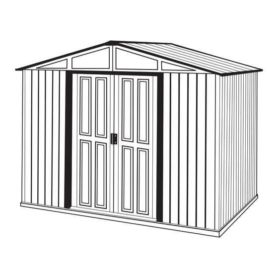
Poly Storage Shed
OWNER'S MANUAL /
Instructions for Assembly
Size 10' x 6'
Ver: 1.0
• Tall Walk in Shed
• Quick & Easy Assembly
• Ridge Reinforced Walls
• Wide Double Doors
• Available in Various Sizes
S H E D S
Requires two people and takes 2-3 hours for Installation.
Customer
Service Hotline
(800) 483-4674
www.uspolymersinc.com
Call us for any missing or damaged parts.
Do not return to the store.
Advertisement

Subscribe to Our Youtube Channel
Related Manuals for DuraMax Duramax


Summary of Contents for DuraMax Duramax
- Page 1 A L L P U R P O S E P O L Y S T O R A G E S H E D S Poly Storage Shed OWNER’S MANUAL / Instructions for Assembly Size 10’ x 6’ Ver: 1.0 Customer Service Hotline (800) 483-4674...
- Page 2 Duramax Storage Shed Limited Ten Year Warranty U.S. Polymer Inc. will send a replacement part free of charge, in the event of material defects and or workmanship for a period of ten years from the date of purchase. This warranty is extended only to the original purchaser. A purchase receipt or other proof of date of original purchase will be required before warranty service is rendered.
-
Page 3: Parts List
PROFILES Parts List Note: Check all parts prior to installation. ACCESSORIES CODE DESCRIPTION CODE DESCRIPTION BLAP BASE BAR BACK LEFT BASE BAR TOP ANGLE BACK (BLAP , BRAP , BSBP) (ABLAP , ABRAP) BRAP BASE BAR BACK RIGHT FCFP FRONT COLUMN FITTING BSBP BASE BAR SIDE CCFP... -
Page 4: Exploded View
Exploded View RC1P RC2P RC2P RF1AP RF4BP RP4AP RF3BP RP2AP RF2AP RP1AP RP1AP RF2AP RP2AP RF3BP RP4AP RF1AP RF4BP SB3AP FSRAP FRAP SB2AP RS4AP FLAP RSBP SB4AP SB1AP FSLAP RSBP FSLAP SB4AP SB1AP SB3AP FLAP RS4AP SB2AP FRAP WP4A FSRAP WP3A ABLAP ASBP... -
Page 5: Parts Needed
Pressure Treated - Wood Studs: DuraMax must be installed on a level wooden platform 2ea 2” x 4” x 90 3/4” (50mm x 101.6mm x 2305mm) or a level concrete foundation. 2ea 2” x 4” x 126” (50mm x 101.6mm x 3200.4mm) 3ea 2”... - Page 6 . Assemble base bar back left (BLAP) and base bar back right (BRAP) with four (S7) screws. See fig. 1 & 2. Note BLAP Take care of sharp edges. BLAP BRAP BRAP Fig.1 Fig.2 . Place the base bar assembly on top of the foundation.
- Page 7 . Using a carpenter square, line up the corners. Secure the base (BSBP) to the foundation with (S1) screws. See blowup. BSBP BSBP . Place the base bar (BBFP) on top of (BSBP) on both sides. Secure with (S7) screw to (BSBP) on both corners.
- Page 8 . Place the entrance taper channel (ECAP) on top of the (BBFP). Secure with (S1) screws to the foundation. See fig. 1 & 2. BBFP ECAP ECAP BBFP BBFP Fig.1 Fig.2 . Measure in all direction as shown in figure. Make the base bar assembly in a perfect square.
- Page 9 . Place the corner column fitting (CCFP) on top of the base bar (BBFP & BSBP). Secure with the three (S1) screws to the base bar. Follow the same at the other corner. BSBP BACK BBFP CCFP CCFP BBFP BSBP BSBP BBFP BBFP...
- Page 10 . Insert the column (COSP) & (COLP) in to corner column fitting and secure with (S1) screws from inside. Insert the column (COSP) at the top of base (BBFP) and column (COLP) at the top of (BSBP) Make sure the direction of the Note column opening and arrow up BSBP...
- Page 11 . Insert the front column fitting at the top of front column (COSP) and secure with (S1) screws from inside. Continue the same at the other side. FCFP Fig.1 FCFP COSP COSP Fig.2 SLAP . Place the sliding channel assembly (SLAP & SRAP) on the top of front column fitting at the both ends.
- Page 12 . Place the wall panel (WP3A) on the base bar (BSBP) front right side of the shed. Line up the holes with base bar. Secure with (S1) screws with washers from out side. First fix the middle screws then WP3A go to the edges.
- Page 13 . Place the right Door column (DCRP) on top of the base bar (BBFP) and insert into the wall panel (WP2A). Line up the holes with wall panel and secure SRAP with (S1) screws. Make sure the door column Note bottom fitting to be inside the door column.
- Page 14 . Fix the column fitting (CFP) to the front column (COSP) with (S1) screws from inside, fix the other end to the Door Column (DCRP) through the wall panel with (S1) screw from inside. CB1P COSP DCRP CB1P Fig.1 Fig.2 .
- Page 15 . Place the wall panel (WP1A) on the base bar (BBFP). Line up the holes with base bar. Secure with (S1) screws. Note Make sure the overlapping position of panels is as shown in fig. 2. WP1A First fix the middle screws (top or bottom) then go to the edges.
- Page 16 . Fix the door column bottom to the fitting (DCBFP) with (S1) Screws. DCLP . Fix the Column fitting (CFP) to the front Column (COSP) with (S1) screw from inside. Fix other end to the Door Column (DCLP) through the WP1A wall panel with (S1) screw from inside.
- Page 17 . Place the Corner Column fitting (CCFP) on top of the base bar at the back side on both corners. Secure with (S1) screws. BACK CCFP CCFP Fig.2 Fig.1 . Insert the column (COLP) into the Corner Column fitting (CCFP) and secure with (S1) screws. Note Make sure the direction of the Column opening and...
- Page 18 . Fix the Column Support (CS) to the columns with two (S7) screws at both corners. COLP COLP Fig.1 Place the wall panel (WP3A) on the base bar side (BSBP) at back left . Line up the hole with base bar and secure with (S1) FRONT screws with washers from out side.
- Page 19 . Place the wall panel (WP3A) on the base bar (BSBP). Line up the holes with base bar and secure with (S1) screws with washer from out side. First fix the middle screws then go to the edges. WP3A BSBP Fig.1 BSBP .
- Page 20 . Place the assembled top angle back in between the column and back wall panel top side. Line up the holes with panel and secure with (S1) screws from outside. ABRAP ABLAP ABRAP Fig.1 ABLAP Fig.2 . Place the top angle side (ASBP) on top of back top angle (ABLAP) and top of sliding channel (SLAP).
- Page 21 . Place the top angle side (ASBP) on top of sliding channel (SRAP) and back top angle (ABRAP) secure with (S1) screws. ASBP See Details. SRAP Fig.1 ASBP ABRAP Fig.2 . Secure the Wall Panel to the top angle with (S1) screws.
- Page 22 . Fix two column fitting with columns to the base bar (BSBP) with (S1) screws from inside. BSBP Fig.1 . Place the Wall Panel (WP4A) on the base bar side (BSBP). Line up the holes with base bar and top angle. 1.
- Page 23 . Fix the Column fitting (CFP) to the Column with (S1) screw as shown. . Fix the Center band (CB2P) to the Column fitting (CFP) with (S1) screw. See the Fig 1. Fix the other end of the Center band to the Center band fitting (CBFP) with (S1) screw.
- Page 24 . Fix the Column fitting (CFP) to the Column with (S1) screw as shown. . Fix the Center band (CB3P) to the Center band fitting (CBFP) with (S1) screw. See fig.1 Fix the other end to the Column fitting (CFP). CB3P Fig.1 CBFP...
- Page 25 . Fix two Column fittings (CBF) with Columns to the other side of base bar (BSBP) with (S1) screws from inside. BSBP BSBP . Place the Wall Panel (WP4A) on the base bar side (BSBP) Line up the holes with base bar and top angle.
- Page 26 . Fix the Center Band (CB3P) to the Column fitting with (S1) Screws. See Fig. 1 Fix the other end to the center band fitting (CBFP) with (S1) screw. See Fig. 2 CB3P Fig.1 CB3P Fig.2 CBFP . Fix the Center Band (CB4P) to the Center Band fitting with (S1) screws.
- Page 27 . Fix the Center Band (CB2P) to the Center Band fitting (CBFP) with (S1) screw . See fig. 1 Fix to other end to the Column fitting (CFP) See fig. 2 CB2P Fig.1 CBFP CB2P Fig.2 . Secure Panel to the Center Bands with (S1) screws with washer from out side.
- Page 28 . Place the Wall Panel (WP4A) on the back base bar. Line up the holes with base bar. 1. Secure the Panel at bottom with (S1) screws to the base bar from out side. 2. Secure the Panel at top with (S1) screws through the top angle to the Column (COLP) First fix the middle screws (top or bottom) then go to the edges.
- Page 29 . Fix two Column fittings (CBF) with Columns to the back base bar with (S1) screws from inside. . Place the Wall Panel (WP4A) on the base bar back. Line up the holes with base bar and top angle. 1. Secure the Panel at bottom with (S1) screws to the base bar from out side.
- Page 30 . Fix the Column fittings (CFP) to the Column as shown. Fig.1 Fig.2 . Fix the Center Band (CB4P) with (S1) screws to the Center Band fitting and column fitting. CB4P CB4P CBFP . Secure the Panels to the Center bands with (S1) screws with washer from out side.
- Page 31 . Place the sliding channel cover (SCAP) on sliding channel and secure with (S7) screws at both ends. SCAP Fig.1 . Place the another half of sliding channel cover (SCAP) on sliding channel and secure with (S7) screws at both ends. IMPORTANT: USE HAND GLOVES TO PREVENT INJURY.
-
Page 32: Parts Needed
C. Roof Note All parts are clearly marked and care should be taken to use the correct one. Parts Needed: (2) Support bracket front right / back left (SB1AP) Roof flashing (RF2AP) (2) Support bracket front left / back right (SB2AP) Roof flashing (RF3BP) - Page 33 . Place the Roof support assembly on top of sliding channel and back top angle. Use (S1) screws to secure. Make 2 Sets. Fig.1 Fig.2 Fig.4 Fig.3 . Assemble the Support bracket (SB3AP & SB4AP) together with Facia bracket support (FBS). Use (S3) bolt &...
- Page 34 . Place the Roof support assembly on top of the sliding channel and back top angle. Use (S1) screw to secure. Fig.1 Fig.2 . Place the Facia support right (FSRAP) on top of Roof support as shown. Secure with (S1) screws to support bracket and top angle side.
- Page 35 . Place the Facia support left (FSLAP & FSRAP) on the top of Roof support as shown. Secure with (S1) screws to Support bracket and top angle side. FSLAP ASBP FSRAP FSLAP FSLAP Fig.1 Fig.2 Fig.3 FSRAP ASBP FSRAP Fig.4 Fig.5 .
- Page 36 . Place the Facia panel (FLAP) at left side and FLAP continue the same. . Place the Facia panel (FLAP) on back side left facia support and fix the Roof plugs with washer and FLAP drive in roof pins. . Place the Facia panel (FRAP) on back side right Facia support and fix the roof plugs with washer and drive in roof pins.
- Page 37 . Place the Roof panel (RP4AP) on top of the Roof support and Facia support. Line up the holes and secure with (S1) screws with washer. RP4AP RP4AP . Place the Roof panel (RP2AP) on the Roof support. Secure with (S1) screws with washer. Make sure the overlapping Note position for roof panel is as...
- Page 38 . Place the Roof panel (RP4AP) on the Roof support and secure with (S1) screws with washers RP4AP . Place the ridge cover (RC1P) on top of Roof panel and fix with Roof plug with washer and drive in Roof Pins.
- Page 39 . Place the Ridge cover (RC2P) on top of Roof panel and fix with Roof plugs with washer and drive in Roof RC2P pins. RC2P . Place the Roof panel (RP1AP) by sliding under the Ridge cover (RC2P) to Roof support. Use (S1) screw with washer to secure.
- Page 40 . Insert the Roof flashing (RF1AP & RF2AP) under the ridge cover. See fig. 1 Line up the holes and fix the roof plug with washer from ridge cover through roof flashing to roof panel drive in the roof pins. See fig. 2 & 3. Use (S3) bolt &...
- Page 41 . Insert the Ridge end cap to the front & back top of the roof and secure with (S1) screws with washer. IMPORTANT: USE HAND GLOVES TO PREVENT INJURY.
- Page 42 D. Door Parts Needed: (1) Door panel (DL1AP) (1) Door panel (DL2AP) (1) Door panel (DR1AP) (1) Door panel (DR2AP) (2) Door panel strip top (DSTAP) (2) Door panel strip bottom (DSBAP) DMSAP DL1AP DR1AP DL2AP DR2AP DVSP DVSP DSTAP DSTAP DMSAP DSBAP...
- Page 43 Right Door Assembly DR1AP . Assemble the door panel (DR1AP & DR2AP) and Door panel middle support (DMSAP) together with (S3) bolt and nut from inside. DR2AP DR1AP DR2AP DMSAP DMSAP . Place the Door panel vertical support (DVSP) to the Door panel (DR1AP) from inside.
- Page 44 . Assemble the Door stopper vertical (DSP) to the Door panel (DR2AP) make sure the side edge of the panel to be inserted into the door stopper profile (DSP). Secure the stopper with Door panel with (S7) screw as shown in fig. DR2AP DR2AP DSTAP...
- Page 45 . Assemble the Door panel strip bottom (DSBAP) with Door panel. Make sure the Door panel bottom edge to be inserted into the (DSBAP). See fig. 1 Secure the strip (DSBAP) with Door stopper (DSP) with (S7) screws. See fig. 2 Secure the Door panel with (DSTBP) use (S7) screws with washer from outside.
- Page 46 . Fix the Door handle (DH) with Door panel from front side with bolt & nut. DL1AP Left Door Assembly DL2AP . Assemble the door panel (DL1AP & DL2AP) and Door panel middle support (DMSAP) together with (S3) bolt and nut from inside. DL1AP DL2AP DMSAP...
- Page 47 . Place the door panel vertical support (DVSP) to the Door panel (DL1AP) from inside secure the panel to the (DVSP). Use (S7) screws with washer from out side DL1AP DL2AP DVSP DL1AP DL1AP DVSP . Assemble to Door stopper vertical (DSP) to the DL1AP Door panel (DL2AP).
- Page 48 . Assemble the Door panel strip top (DSTAP) DSTAP with Door panel. Make sure the Door panel top edge to be inserted into the (DSTAP). Secure the Door panel strip top (DSTAP) with Door stopper (DSP) with (S7) screws. See fig. 1&2. Secure the Door panel with (DSTAP) use (S7) screws with washers from out side.
- Page 49 . Assemble to bottom slider (BS) to the Door panel bottom side at both edge with (S3) bolt and nut with washers. . Fix the Door handle (DH) with Door panel from front side with bolt & nut. IMPORTANT: USE HAND GLOVES TO PREVENT INJURY.
- Page 50 . Slide the Door panel assembly into the base bar front (BBFP). Make sure the bottom slider (BS) should slide inside the base bar front. See fig. 1. Fix the Door panel top to the top slider (TS) with (S1) screws.
- Page 51 . Cut the Edging Profile (EDP) to the required length and insert to the Sliding Channel joint (SJP) to prevent injury. See fig. . Cut the Edging Profile (EDP) to the required length and insert to the Facia Bracket Support (FBS) to prevent injury.
Need help?
Do you have a question about the Duramax and is the answer not in the manual?
Questions and answers