Advertisement
Quick Links
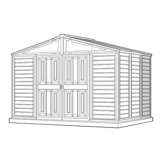
Storage Shed
Storage Shed
OWNER'S MANUAL /
Instructions for Assembly
Size 8'x 6' with "Extension Kits"
Ver: 2.0
Your Total Solution To maintenance Free Storage Sheds.
• All Weather Durable PVC
• Won't Dent, Rust, Rot or Mildew
• Never Needs Painting
• 61" Wide Double Doors
• Easy Assembly
• High Wind Tested
• Snow Load Tested 20lbs/sq.foot
• Pad Lock Ready (Lock not included)
• Wooden or Cement Foundation Needed
Available Kits
• Foundation Kit Available
• Modular 2.5' Extension Kits Available
• 8'x6' Window Kits Available
PART 1
ASSEMBLING SHED WITH EXTENSION KIT
PART 2
ADDING EXTENSION KIT TO EXISTING SHED
Note: For shed with extension use this manual only.
Requires two people and takes about 4-5 hours for Installation.
Patent #416.091
Customer
Service Hotline
(800) 483-4674
www.uspolymersinc.com
Call us for any missing or damaged parts.
Do not return to the store.
Advertisement

Related Manuals for DuraMax Storage Shed


Summary of Contents for DuraMax Storage Shed
- Page 1 Storage Shed Storage Shed Patent #416.091 OWNER’S MANUAL / Instructions for Assembly Size 8’x 6’ with “Extension Kits” Ver: 2.0 Customer Service Hotline (800) 483-4674 www.uspolymersinc.com Your Total Solution To maintenance Free Storage Sheds. PART 1 • All Weather Durable PVC •...
-
Page 2: Limits And Exclusions
Duramax Storage Shed Limited Fifteen Year Warranty U.S. Polymer Inc. will send a replacement part free of charge, in the event of material defects and or workmanship for a period of fifteen years from the date of purchase. This warranty is extended only to the original purchaser. A purchase receipt or other proof of date of original purchase will be required before warranty service is rendered. - Page 3 8’ x 6’ Parts List Note: Check all parts prior to installation. ACCESSORIES CODE DESCRIPTION CODE DESCRIPTION LEFT DOOR COLUMN RIGHT DOOR COLUMN (CDLB) (CDRB) B1LB FRONT ‘U’ CHANNEL LEFT FDCL DOOR COLUMN FITTING LEFT FDCR DOOR COLUMN FITTING RIGHT B1RB FRONT ‘U’...
- Page 4 8’ x 6’ Exploded View FPLB FPRB RS2B RS3B RS5B RS10B RS4XB RS2B RS11B RS10B RS2B RS4XB RS12B RS5B RS1XB RS2B RS3B RS8B FPRB RS9B RS1XB FPLB CB3B CB3XB CB2B CB1B B1RB CB1B CB2B B1LB CDRB CB1B CB4B CB4B CDLB...
- Page 5 One Extension Parts List Note: Check all parts prior to installation. CODE DESCRIPTION EXTL EXTENSION ‘U’ CHANNEL LEFT EXTR EXTENSION ‘U’ CHANNEL RIGHT MIDDLE COLUMN CB3LB BACK CENTER BAND LONG MIDDLE COLUMN FITTING MIDDLE COLUMNS (CMB) (FMC) RS3SB RS3 ROOF STRUCTURE SHORT RS4B RS4 ROOF STRUCTURE RS6B...
- Page 6 Exploded View with One Extension RS12B RS7B RS13B RS3SB RS13B RS6B RS4B RS13B RS13B RS3SB RS4B RS11B RS13B CB3LB EXTR CB3LB EXTL...
-
Page 7: Parts Needed
Wooden Platform (Not Included) are followed step by step. The following are a list of lumber and sizes you will need. DuraMax must be installed on a level wooden platform Pressure Treated - Wood Studs: Exterior Grade (CDX): or a level concrete foundation. - Page 8 . Using a carpenters square, line up all corners. Secure base to wood foundation using (S1) screws Concrete foundation . Shed or shed foundation should be placed on concrete footing by use of anchor bolt and nut. Using a carpenters square, line up corners. Align U-Channel base, mark the concrete through the holes in the base and drill concrete with 1/2”...
- Page 9 . Insert the front side panel (FSP ) into the groove of column (CDRB). Start at the bottom of the panel at an angle then push into place. Always place panels into frame at an angle Note on top and slide in sideways and downward CDRB for easy insertion.
- Page 10 .To stabilize the front panel attach the front center & band right (CB1B). Start with the center band fitting. CB1B Fix to corner column (CCB) with (S2) screws. To continue See figures (fig.1) (fig.2) and (fig.3). To insure easy assembly Locate the identification number of each CDRB part.
- Page 11 . Assemble back center bands (CB3B) and (CB3XB) with middle joining support (MJ). Use (S1) screws. CB3B CB3B CB3XB CB3XB . Assemble the center bands (CB2B) & (CB3LB) with (S3) screws with nuts. Follow Overlapping Method shown below. Make 2 sets. Add one (CB3LB) for each extension.
- Page 12 Working from inside, continue connecting the side panels (SP ) and columns (CMB) in sequence along (B2B) & (EXTR) base. Use (S1) screws to fix columns to base. For each extension add one side panel (SP ) and one middle column (CMB) in extension base U-channel (EXTR) &...
- Page 13 . Stabilize the side panels with center bands (CB3LB) & (CB2B). Fix the center band fitting (FCB) to corner column (CCB) See Fig.1 Follow the Fig. 2, 3, 4 & 5. & CB3LB CB2B CB1B CB2B EXTR Inside CB1A Fig.1: Use (S2) Fig.
- Page 14 . Continue connecting the back panels and columns in sequence along base (B22) and (B21). Fix columns to base with (S1) screws. Back Wall Fix the corner column (CCB) to last panel and base. EXTL Inside . Working from outside use (S1) screws to secure the corner column (CCB) to bases (B21) and (EXTL).
- Page 15 . Stabilize the side panels with center bands (CB3B & CB3XB). Fix the center band fitting (FCB) to corner column (CCB) see figure 1. Follow figures 2, 3, 4 and 5. 3 & 6 & CB3B CB3XB CB3B CB3XB CB2B CB3B CB3XB CB1A...
- Page 16 Working from inside, continue connecting the side panels (SP ) and columns (CMB) in sequence along (B2B) & (EXTL) base. Use (S1) screws to fix columns to base. EXTL B1LB Inside Slide corner column (CCB) into side panel (SP ) pushing the column to the side panel.
- Page 17 . Stabilize the side panels with center bands (CB3LB) & (CB2B). Fix the center band fitting (FCB) to corner column (CCB). See Fig.1 Follow the Fig. 2, 3, 4 & 5. & CB3XB CB2B CB3LB CB3LB CB1A Fig.1 : Use (S2) Fig.2: screw.
- Page 18 . Insert the side panel (FSP ) into the groove of column (CCB). Start at the bottom with panel at an angle then push into place. B1LB B1LB Inside . Slide door column (CDLB) into the U-Channel Base (B1LB) on the left side of the door. Line up the pre-drilled holes on (CDLB) Column with pre- drilled holes on U-Channel Base (B1LB).
- Page 19 . Fix the center band (CB4B) to (CDLB) and base (B1LB). See Fig. 1, 2 and 3. CDLB CB1B CB1B CB1B CB4B CB4B CDLB B1LB CB4B CDLB CB4B Fig.2: Fig.1: (S1) screw. Fig.3: Fix the (EPS) (S1) screw. Fix (CB4B) to B1LB at the end of Fix (CB4B) to...
- Page 20 . Insert the middle column fitting (FMC) into top of the middle columns (CMB). Fix the column to fittings with (S1) screws from inside the shed. Inside Inside . Insert the corner column fittings (FCC) into the corner columns (CCB). Fix with (S1) screws from out side of the shed.
- Page 23 Front roof structure assembly . Assemble front roof structures (RS1XB) 2nos. and middle joining support (MJ) together with 4 (S1) screws as shown in fig. RS1XB RS1XB RS1XB RS1XB RS9B . Assemble roof support (RS8B) and (RS9B) to (RS1XB) assembly with only 4 (S1) screws. RS1XB RS8B RS9B...
- Page 24 Back roof structure assembly . Assemble back roof structures (RS1XB) 2 nos. and middle joining support (MJ) together with 4 (S1) screws . RS1XB RS1XB RS1XB RS1XB RS9B . Assemble roof support (RS8B) and (RS9B) to (RS1XB) assembly with 8 (S1) screws. RS8B RS1XB RS9B...
- Page 25 . Assemble (RS3B) & (RS3SB) with (S1) screws (2 sets). & RS3SB See fig 1. RS3B & . Insert 90 degree joint (RJ) into the (RS3B) U- channel Roof support. Use a hammer to push in. Use (S1) screws to fix. Repeat on other end of (RS3SB). See fig.2 and fig.3.
- Page 26 . Assemble the roof structure(RS5B) & (RS6B) into roof structure (RS13B) with 8(S3) screws with nuts at both ends. Make 2 sets. This step 13 applies only for Ver: 2.0 Extension kits. Note If you have a Ver: 1.1 extension kit, the RS13B part will not be in the extension kit and you can skip this step.
- Page 27 Place the assembled front roof structure into position on top of door columns. Line up pre-drilled holes with door column fittings (FDCL) & (FDCR). Use (S1) screws to fix front roof structure to the door columns with left and right door fittings. Front Inside Of Shed FDCR FDCL...
- Page 28 Place the assembled back roof structure into position on top of columns (CMB). Line up pre-drilled holes with column fittings (FMC). Use (S1) screws to fix back roof structure to (FMC). Inside Back of Shed Make sure front and back Note assembly, the (RS2B ) roof structure position towards...
- Page 29 . Insert the 90 degree joint (RJ) (Assembled with roof support RS3B & RS3SB) in to the roof structure (RS1XB). See fig. Follow Fig. 2 and 3. RS3SB After assembly make sure this roof Note structure’s U-Channel is positioned RS3B down.
- Page 30 Fix the (RS3B) & (RS3SB) to middle column fitting (FMC) with (S1) screws. fig.1 to 4 Place the assembled roof structure (RS5B) & (RS6B) into position on roof structure supports (RS8B) at the left side of the shed. Use (S1) screws to fix. See Fig.1 &...
- Page 31 RS6B RS13B RS13B RS7B RS7B RS5B RS6B Place the assembled roof structure (RS5B) & (RS6B) into position on roof RS7B structure supports (RS9B) at the left side of the shed. Use (S1) screws to fix. RS5B See Fig.1 & Fig.2 RS5B Place the assembled roof structure (RS5B) &...
- Page 32 . Attach the roof structures (RS4XB) to (RS3B) with (S1) screws. see fig. 1 & 2. . Attach the roof structures (RS4XB) to (RS5B), (RS6B) assembly and (RS5B), (RS7B) RS4XB assembly with (S7) screws. see fig. 3 & 4. RS3B RS4XB RS5B RS4XB...
- Page 33 . Attach roof structure support (RS10B) and (RS11B) to roof structures (RS5B), RS10B (RS6B) & (RS7B) using (S1) screws. See RS11B (fig.1), (fig.2) and (fig.3). Add one (RS11B) for each extension. RS11B RS10B RS11B RS10B RS11B RS10B Make sure the hole in (RS10B) Note face outward on both side.
- Page 34 . Attach the roof structures support (RS12B) with (RS5A) and (RS5A) with (S1) screws. See fig.1 and 2. RS12B This step 27 applies only for Ver: 2.0 Note Extension kits. If you have a Ver: 1.1 extension kit, the RS12B part will not be in the extension kit and you can skip this step.
- Page 35 D. Roof panels Parts Needed For Each Extension: Parts Needed: Front (4) Roof Panels (RP ) (2) Roof Panels (RP ) (2) Facia Panel Left (FPLB) (1) Ridge Cover (RRS) (2) Facia Panel Right (FPRB) (16) Roof Plugs w/Washer (PPG) (2) Ridge Cover (RRS) (16) Roof Pins...
- Page 36 Fig.3 Fig.2 Fig.5 Fig.4 FPRB Fig.6 Fig.7 Front of Shed Fig.8 Fig.9...
- Page 37 Insert the sagging support (RS14B) from inside the shed by sliding in between roof structure (RS5) and roof panel until it reaches (RS3) roof structure for each panel. See fig.1. Insert the sagging support (RS14B) from inside the shed by sliding in between roof structure (RS5) and roof panel until it touches the other roof structure.
- Page 38 Note: To prevent water leakage it is important that these instructions are followed. After completing the assembly apply silicone around the perimeter of the base U-channel. Seal the corners, joints and base of door column also. Inside Base U-channel After completing the panel assembly, apply silicone around the roof plugs.
-
Page 39: Side View
F. Optional Ventilation Kit ACCESSORIES CODE DESCRIPTION VENTILATION COVER VENTILATION COVER PIN VENTILATION COVER (VC) VENTILATION COVER PIN (VCP) TOOLS YOU WILL NEED Power Drill Dia 5/32” (4.2mm) drill bit Dia 1/2” (12.5mm) drill bit Optional ventilation kits can be installed on any of the wall panels. - Page 40 High wind area installation instructions Note: To ensure that your shed withstands high winds, you will need the following reinforcement. Parts needed: Parts needed for each extension: CODE DESCRIPTION CODE DESCRIPTION DIA. 4.2 x 16mm. (5/32” x 5/8”) DIA. 4.2 x 16mm. (5/32” x 5/8”) SHEET METAL SCREW (not included with shed) SHEET METAL SCREW...
- Page 41 Important Warranty Information The Duramax shed has been tested and passed wind loads of up to 115 mph in a controlled laboratory environment. Natural high wind areas create wind at unpredictable speeds that are very difficult to capture accurately by location. As such we cannot guarantee the performance...
- Page 42 PART 2: Adding Extension Kit to Existing Shed Back Front Note Remove this Ridge cover. Remove one ridge cover (RRS) from the back side . See the figure. Use a drilling machine to remove the pins and plugs from the ridge cover, roof panel and facia panel. Care should be taken not to damage the panels.
- Page 43 Remove the roof plugs (PPG) and pins (PIN) from backside facia panel and detach it from the shed. FPRB FPLB Support the roof structure (RS5B) & (RS5B) by using an appropriate support to avoid the roof Support structure from collapsing. Support not included.
- Page 44 Detach (RS2B) from (RS5B). Then detach (RS5B) from (RS8B). RS5B RS2B RS5B RS8B RS8B Back Inside Detach (RS2B) from (RS5B) then (RS5B) from (RS9B) See fig.1 and fig.2. RS2B RS2B RS5B RS5B Inside Inside RS9B RS9B Right Left fig.1 fig.2...
- Page 45 Detach roof structure (RS2B) from roof structure (RS3B) from both corners. See fig.1. Detach 90-degree joint (RJ) from corner column fitting (FCC) from both corners. See fig.2. Detach (RS3B) from 90-degree joint (RJ) from both corners. See fig.3. RS2B RS3B RS3B fig.1 fig.2...
- Page 46 Detach the center bands (CB3XB) & (CB3B) assembly from the back wall of the shed. Follow the figures. CB3B CB3XB CB2B CB3B CB1A Fig.1: Detach (CB3B) from Inside back wall (CB2B). Then detach (CB3B) & (CB2B) from (FCB). CB3B CB3XB CB3XB CB3XB CB2B...
Need help?
Do you have a question about the Storage Shed and is the answer not in the manual?
Questions and answers