
Subscribe to Our Youtube Channel
Related Manuals for Smooth Fitness 7.25


Summary of Contents for Smooth Fitness 7.25
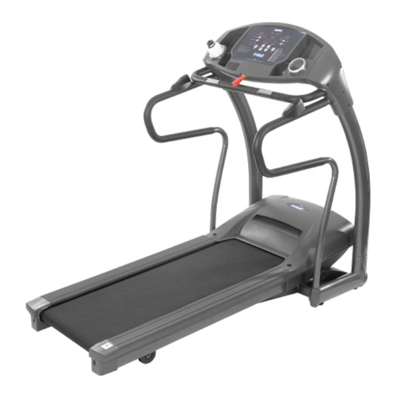
- Page 1 USER’S MANUAL 7.25 MOTORIZED TREADMILL MODEL NUMBER: 7.25 USER WEIGHT LIMITATION: 350lbs (160 kgs) SERVICE NUMBER: 0800-09 72100 SERIAL NUMBER (found on frame):...
- Page 2 • Place on a level surface, with 6 feet (2 m) of clearance behind it. Do not place the treadmill on any surface that blocks air openings. To protect the floor or carpet from damage, place a mat under the treadmill.
-
Page 3: Power Requirements
(not included) with your treadmill. This treadmill must be grounded to reduce the risk of electrical shock. Grounding provides a path of least resistance for electric current, should the treadmill malfunction. This treadmill comes with an electrical cord having an equipment-grounding conductor and a grounding plug. -
Page 4: Pre-Assembly
Always check the easily wear components like pulley ets. To prevent danger. There is an emergency stop to prevent dangers, you can stop the treadmill immediately by actuated the emergency stop for emergency dismount. 350lbs (160kgs) -
Page 5: Contents Checklist
CONTENTS CHECKLIST Carton contents: For your convenience, we have identified the contents of the shipping carton. Please check to make sure you have all of the components before assembly. This chart is provided to help you identify the components used in the assembly of this product. Description Computer Front Handlebar Assembly... -
Page 6: Hardware Comparison Chart
7.25 TREADMILL HARDWARE COMPARISON CHART Hardware chart: For your convenience, we have identified the hardware used in the assembly of this product. This chart is provided to help you identify those items that may be unfamiliar to you. Description M8 x 15mm Bolt... -
Page 7: Parts List
PARTS LIST Description Console Assembly 7.25-100 Overlay 7.25-101 Computer Insert 7.25-102 Console PC Board 7.25-103 Console Housing - Upper 7.25-104 Console Housing - Bottom 7.25-105 Safety key Base 7.25-106 Safety Key 7.25-107 Safety Key Wire - Upper 7.25-108 Computer Wire - Upper 7.25-109... - Page 8 7.25 TREADMILL PARTS LIST Computer Wire - Upper 7.25-307 Motion Control Sensor Wire - Middle 7.25-308 7.25-400 Base Frame 7.25-401 Safety Key Wire - Lower 7.25-402 Computer Wire -Lower 7.25-403 Power Switch Plate Cover 7.25-404 Power Switch Plate 7.25-405 Power Breaker 7.25-406...
- Page 9 PARTS LIST Driving Belt 7.25-506 Motor Control Board 7.25-507 Elevation Control Board 7.25-508 Elevation Support Tube 7.25-509 ELEVATION SUPPORT TUBE COVER - LEFT 7.25-510 MOTOR BOTTOM COVER 7.25-511 DECK FRAME SIDE COVER - LEFT 7.25-512 PLASTIC CLAMP - TOP 7.25-513 PLASTIC CLAMP - BOTTOM 7.25-514...
- Page 10 7.25 TREADMILL PARTS LIST #8 × 12mm Screws 7.25-803 M8 x 15mm Bolt 7.25-804 M8 x 50mm Bolt 7.25-805 #8 x 19mm Screw 7.25-806 #8 x 19mm Screw 7.25-807 M5 × 10mm Screws 7.25-808 #8 × 16 Screws 7.25-809 C Fixed 7.25-810...
- Page 11 PARTS LIST Description C Fixed 7.25-837 M10 × 43mm Bolts 7.25-838 Cushion Pad 7.25-839 M10 × 40mm Screws 7.25-840 M6 × 10mm Screws 7.25-841 M10 × 52mm Screws 7.25-842 www.smoothfitness.com Qty. Order No. 7.25-837 IR-BOLT-06-03-M10C 7.25-838 IR-BOLT-01-10-M10X42 7.25-839 AP-006 7.25-840 IR-BOLT-01-05-M10X40X15 7.25-841...
-
Page 12: Parts Diagram
7.25 TREADMILL PARTS DIAGRAM A MAJORITY OF THE PARTS SHOWN HERE HAVE BEEN PRE-ASSEMBLED AT THE FACTORY. - Page 13 www.smoothfitness.com PARTS DIAGRAM A MAJORITY OF THE PARTS SHOWN HERE HAVE BEEN PRE-ASSEMBLED AT THE FACTORY.
- Page 14 7.25 TREADMILL PARTS DIAGRAM A MAJORITY OF THE PARTS SHOWN HERE HAVE BEEN PRE-ASSEMBLED AT THE FACTORY.
- Page 15 www.smoothfitness.com PARTS DIAGRAM A MAJORITY OF THE PARTS SHOWN HERE HAVE BEEN PRE-ASSEMBLED AT THE FACTORY. 812 408...
- Page 16 7.25 TREADMILL PARTS DIAGRAM A MAJORITY OF THE PARTS SHOWN HERE HAVE BEEN PRE-ASSEMBLED AT THE FACTORY. 505 823 515 520...
- Page 17 www.smoothfitness.com PARTS DIAGRAM A MAJORITY OF THE PARTS SHOWN HERE HAVE BEEN PRE-ASSEMBLED AT THE FACTORY.
- Page 18 7.25 TREADMILL PARTS DIAGRAM A MAJORITY OF THE PARTS SHOWN HERE HAVE BEEN PRE-ASSEMBLED AT THE FACTORY.
- Page 19 ASSEMBLY STEP 1: Remove your treadmill from the carton and place it on the floor in an open area. Connect the Middle Section Computer Wire (307) to the Lower Section Computer Wire (403) and the Middle Section Safety Key Wire (306) to the Lower Section Safety Key Wire (402).
- Page 20 7.25 TREADMILL ASSEMBLY STEP 2: First connect the Motion Control Wire Middle Section (308) to Motion Control Wire Lower Section (208) as shown. Insert the Handlebar (201) into the Upright Tube (301) and secure using two M8 x 15mm Bolts (804), Four M8 x 50mm Bolts (805) and attach Handlebar Lower Cover...
- Page 21 www.smoothfitness.com ASSEMBLY STEP 3: Attach the Front Handlebar (204) on the Upright Tube (301) and secure using four M8 x 50mm Bolts (805).
- Page 22 7.25 TREADMILL ASSEMBLY STEP 4: Connect the Upper Section Computer Wire (109) to the Middle Section Computer Wire (308) and the Upper Section Safety Key Wire (108) to the Middle Section Safety Key Wire (307). Connect the Upper Section Hand Pulse Wires (111) to Lower Section Wires (207) and Upper Section Motion Control Wires (115) to Lower Section Wires (308) for each side.
- Page 23 ASSEMBLY STEP 5: First Fix the Ground Wire (110) to the Upright Tube (301) and secure using one #8 x 19mm Metal Screws (807). Attach the Upright Cover RR (305) and the Upright Cover LL (302) to the Upright Tube (301). Secure using four #8 x 19mm Screws (806) and four #8 x 19mm Metal Screws (807).
- Page 24 7.25 TREADMILL ASSEMBLY STEP 6: Secure by tightening the Fix Bolts Sets (412). The Fix Bolts Sets (412) are pre-assembled to the Base Frame (401) at the factory.
-
Page 25: Stabilizer Adjustment
FOLLOW THESE INSTRUCTIONS TO LEVEL YOUR TREADMILL: An uneven floor or improper stabilizer level can cause the treadmill to wobble during use as well as the incline adjustment to function incorrectly. Please follow the procedure described below to make sure the treadmill stabilizer is adjusted correctly prior to use. -
Page 26: Folding Instructions
7.25 TREADMILL FOLDING INSTRUCTIONS How to fold treadmill: Treadmill can be folded for space saving storage. To do this follow instructions here: Lift the deck carefully from rear You will hear a click sound when the lock engages. -
Page 27: Unfolding Instructions
UNFOLDING INSTRUCTIONS How to unfold treadmill: To unfold treadmill for use follow the instructions here: Release Lever Lift the deck froTip the release lever with your foot…portation wheels. … and carefully let down the deck www.smoothfitness.com... -
Page 28: Transport Instructions
TRANSPORT INSTRUCTIONS: To roll away for storage simply grab the rear deck, lift slightly and roll to desired location. Lift the deck from the rear so that the treadmill rests on the front transportation wheels. Roll to a desired location. -
Page 29: Button Functions
Time/Distance/Height Metric/English Incline Up/Down Custom Program Save Preset Programs Speed Up/Down BUTTON FUNCTIONS: START Press to start exercise at an initial speed of 0.5 mph / 0.8 km/h. STOP / ENTER a. Press to confirm program and preset function values during setting mode. b. -
Page 30: Computer Operation
SAFETY KEY The safety key must be inserted into the slot on the console in order to operate the treadmill. Always insert the safety key and attach the clip to your clothing at your waist before beginning your workout. If you should encounter problems and need to stop the motor quickly, simply pull on the cord to disengage the safety key from the console. - Page 31 User’s can record their fitness rating to use for reference. To start the Fitness- Test, press the “Fitness-Test ” button toward the end of a workout (while your pulse is still under trainings load). The treadmill will enter the PAUSE/STOP status.
- Page 32 7.25 TREADMILL COMPUTER OPERATION SELECT OPERATING PROGRAM After completing the user information set up the SPEED PROFILE LED window will show “P1”. Press the SPEED UP/DOWN buttons to select a P1 – P8 program or C1-C3 user program then press the STOP/ENTER button to confirm. Prior to starting the selected program, follow the procedure to operate the different programs as below: PROGRAM 1 –...
- Page 33 COMPUTER OPERATION PROGRAM 4 – INTERVAL INCLINE If P4 is selected, the TIME LED window shows the factory setting value “24:00” and the PULSE/INCLINE LED window shows a blinking “L 1”. Press the SPEED UP/DOWN buttons to select the intensity of workout from L1 to L12 then press the STOP/ENTER button.
- Page 34 30 seconds. If the actual user’s pulse does not reach 85% of the max. heart rate then the incline level will be increased by 1 level every 30 seconds. If the actual user’s pulse reaches 85% of the max. heart rate then the treadmill performance will be remain unchanged.
- Page 35 Press the START button again during the cool down session and the treadmill will skip the cool down procedure and continue running at a speed of 3.2 km/h / 2.0 mph and incline of level 0.
- Page 36 7.25 TREADMILL COMPUTER OPERATION USING THE CHEST BELT HEART RATE MONITOR (optional feature dependant on model purchased): For proper operation, the chest belt should be worn across the front of your body just below the chest line as shown in the drawing.
-
Page 37: Motion Control Operation
• Always switch off the motion control function by pressing the MOTION CONTROL button on the console before turning off the power to the treadmill. www.smoothfitness.com 2. Use right sensor to speed up. 3. Use left sensor to slow down. - Page 38 1/4 turn in the clockwise direction. Plug the power cord back into the surge protector and run the treadmill at 2.5 mph. You should now walk on the belt to determine if the belt is still slipping.
-
Page 39: Deck Lubrication
While lifting the side of the walking belt, position the spray nozzle between the walking belt and the board approximately 6" from the front of the treadmill. Apply the silicone spray to the walking board, moving from the front of the treadmill to the rear. -
Page 40: Warranty
7.25 TREADMILL Read and follow the Assembly-instructions and the User’s-Manual before using this product. Warranty Coverage: Smooth Fitness GmbH ("Smooth Fitness") warrants to the original owner that each new product to be free from defects in workmanship and material. This warranty is limited on home use only. -
Page 41: Important Steps
IMPORTANT STEPS Warning: Before using this product, please consult your personal physician for a complete physical examination. Frequent and strenuous exercise should be approved by your doctor first. If any discomfort should result from your use of this product, stop exercising and consult your doctor. -
Page 42: Target Heart Rate
7.25 TREADMILL TARGET HEART RATE Finding your pulse: To make sure your heart is beating in its target zone, you’ll need to know how to monitor your heart rate. The easiest way is to feel the pulse in the carotid artery on either side of your neck, between the windpipe and the large neck muscles. Count the number of beats in ten seconds, and then multiply that number by six. -
Page 43: Muscle Chart
MUSCLE CHART Targeted muscle groups: The exercise routine that is performed on this product will develop primarily lower body muscle groups. These muscle groups are shown in gray color on the chart below. Shoulder muscles Pectoral muscles Bicep muscle Abdominal muscles Forearm muscles Quadricep muscles www.smoothfitness.com... -
Page 44: Stretching Routine
7.25 TREADMILL STRETCHING ROUTINE Warm up and cool down: A successful exercise program consists of a warm-up, aerobic exercise, and a cool-down. Do the entire program at least two and preferably three times a week, resting for a day between workouts. After several months, you can increase your workouts to four or five times per week. -
Page 45: Troubleshooting
2. Check the circuit breaker reset switch located on the front of the treadmill. Turn the power off, wait 5 minutes then press the rest switch. 3. Check the house electrical breaker box and the circuit breaker for the room the treadmill is located in. If it has tripped, reset or have an electrician replace the breaker in home. - Page 46 Smooth Fitness PO BOX 436 Farnborough GU14 4BS United Kingdom Phone: 0800-09 72 100 e-mail: info@smoothfitness.co.uk Website: www.smoothfitness.co.uk Copyright © 2005 Greenmaster Industrial Corp. All rights reserved.
Need help?
Do you have a question about the 7.25 and is the answer not in the manual?
Questions and answers