Table of Contents
Advertisement
Quick Links
Advertisement
Table of Contents

Related Manuals for Meyra 1.736


Summary of Contents for Meyra 1.736
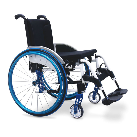
- Page 1 OPERATING MANUAL FOLDING WHEELCHAIR, MODEL 1.736 m o v e p e o p l e .
-
Page 2: Table Of Contents
Contents Introduction ....................6 Acceptance ....................7 Adaptation ....................7 Handling the wheelchair ................7 Specifi cations ......................7 Use .........................8 Auxiliary drives .....................8 Overview ....................... 9 Driving behaviour ..................10 Safety information .....................10 Supplementary user/safety information ............10 Brake ......................12 Pressure brakes ....................13 Locking the pressure brakes .................13 Releasing the pressure brakes ..............13... - Page 3 Height-adjustable leg support ................22 Folding up the foot plates ................22 Swivelling off and removal of the leg supports .........22 Attaching the leg supports ................23 Height adjustment of the leg support ............23 Adjusting the height of the footplate ............24 Depth adjustment of the calf cushion ............24 Armrests ......................
- Page 4 Wheels ......................38 Drive wheels .......................38 Quick release axle ..................38 Handrims ......................39 Steering wheels ....................39 Tyres ........................39 Support castors ..................40 Swivel-away support castors ................40 Swinging the support castors ...............40 Insertable anti-tip castors ..................41 Removing/attaching the support castor ............41 Adjusting the support castor ...............41 Correct support castors length ..............41 Manoeuvre rollers ..................
- Page 5 Loading and transportation ..............50 Safety information ..................50 Transport in vehicles ..................50 Transport security ..................50 Transport in handicapped transport automobile ..........51 Maintenance ....................53 Cleaning and Care ....................53 Upholstery and covers ..................53 Plastic parts ....................53 Finish ......................53 Chassis ......................54 Disinfection ......................54 Reinstallment ......................54 Maintenance ....................
-
Page 6: Introduction
☞ Note: ing a wheelchair from this series. Please note that the illustrated The model 1.736, fulfi ls the wish for equipment variants can deviate mobility and more independence by from your model. way of a new styling of the proven –... -
Page 7: Acceptance
HANDLING THE WHEEL- CHAIR All products are checked for faults in the factory and packed in special Specifi cations boxes. The wheelchair, model 1.736 was de- ☞ Note: veloped for adults and adolescents. ☞ However, we request that you Three frames are available: check the vehicle for possible –... -
Page 8: Use
Auxiliary drives Through its constructive advantages Before attaching auxiliary drives the the wheelchair can universally be following notes have to be consid- implemented on hard surfaces and ered: therefore an allround-wheelchair: Attention: – for indoors (e.g. apartment, day Attachment of auxiliary drives may care), only be done on wheelchair mod- els cleared for these. -
Page 9: Overview
OVERVIEW The overview shows the most important components of the wheelchair. Pos. Description Pos. Description 1 Back support 9 Push handle 2 Arm support 10 Side element 3 Seat cushion 11 Handrims 4 Leg support 12 Drive wheel 5 Calf strap 13 Tilt aid 6 Footrest 7 Steering wheel... -
Page 10: Driving Behaviour
DRIVING Supplementary user/safety information Alignment of the driving behaviour • Clean, passive lighting is required and the personal abilities is to be car- for driving in public traffi c. ried out together with your specialist • Do not throw or drop parts belong- dealer or therapist and is achieved af- ing to the wheelchair! –... - Page 11 • Never leave children/adolescents in • Tyres are made of a rubber mix- wheelchairs unsupervised. ture and can leave permanent or diffi cult-to-remove marks on some • Always approach small obstacles, surfaces (e.g. plastic, wooden or e.g. steps or curbs, slowly and at a parquet fl...
-
Page 12: Brake
BRAKE By locking the brakes the wheelchair is to secured against unintentional rolling off (parking brake). The locking brake belongs to the most important safety features of a wheel- chair and is available as a pressure brake (1). Attention: Please observe the maintenance instructions as well as instructions Attention: in the section <... -
Page 13: Pressure Brakes
Pressure Brake A metered braking from driving speed (operating brake) is possible with the brake levers (1) of the pres- sure brakes. Service brake Press the two brake levers evenly only slightly to the front, this brakes the wheelchair in a metered fashion. Locking the pressure brakes To secure the wheelchair against any unintentional rolling, press both brake... -
Page 14: Drum Brake For Attendant
Drum brake for attendant A metered braking from driving speed (operating brake) is possible with the brake levers of the drum brakes. The wheelchair is also to be secured against unintentionally rolling away (parking brake) by engaging these brakes. Locking the drum brakes Pull both brake levers evenly to secure the wheelchair against unintentional rolling away. - Page 15 Loosen the drum brakes Pull both brake levers (1) until the latches (2) automatically jump out of the lock. Release both brake levers. – The park- ing brakes are release and the wheel- chair ready to go. Attention: For driving the front and rear brake levers must be disengaged.
-
Page 16: Leg Supports
LEG SUPPORTS Attention: Do not use the leg supports to lift or carry the wheelchair. • The parking brakes are to be en- gaged before all assembly work. – This prevents the wheelchair from rolling away accidentally. Calf strap The calf strap (1) prevents the feet from sliding off of the footplates. -
Page 17: Folding Up The Footplates
Folding up the footplates The footplates are to be folded up for entry into, exiting the wheelchair or scuttling (forward motion of the wheelchair with the feet) (1). Turning the leg supports to the side For easy transfer out of/into the wheelchair as well as driving closer to a closet, bed or bathtub the leg sup- ports can be swivelled away toward... -
Page 18: Dismantling The Leg Supports
Removing the leg supports For easy transfer into and out of the wheelchair as well as a reduced wheel- chair length (important for transport) the leg support can be removed (1). ☞ Note: Before swivelling the leg support loosen or remove the calf belt on one side. -
Page 19: Adjusting The Height Of The Footplate
Adjusting the height of the foot- plate Remove the clamping screw (1) to ad- just the height. Telescope the foot plate to the de- sired height and then secure it with the clamping screw. Angle adjustable footplates After loosening the clamping screw (2) pull out the dovetail connection and adjust the angle of the footplates. -
Page 20: Continuous Leg Support
Continuous leg support The footboard of the continuous leg support (1) can be folded up to the side. Folding up the foot board For an unobstructed foot area, fold up the left side of the foot board to the right as far as it will go (2). Folding down the foot board Fold down the left side of the foot board until it rests on the foot board... -
Page 21: Adjusting The Height Of The Footboard
Adjusting the height of the foot- board Loosen the clamping screw (1) to ad- just the height. Telescope the footboard to the de- sired height and then retighten the screw. Angle adjustable footboards After loosening the clamping screw (2) pull out the dovetail connection and adjust the angle of the footplates. -
Page 22: Height-Adjustable Leg Support
Height-adjustable leg sup- port Folding up the footplates For entry and exiting the footplates (1) are to be folded up and the calf cushions (2) swivelled outward in driv- ing direction. Swivelling off and removal of the leg supports For easy transfer out of/into the wheelchair as well as driving closer to a closet, bed or bathtub the leg sup- ports can be swivelled outward and... -
Page 23: Attaching The Leg Supports
Attaching the leg supports With the leg support in a swivelled- aside position, hang it in and then swivel it to the front until the locking device audibly latches. ☞ Note: After swivelling the leg support in- ward again do not forget to check the corresponding locking device. -
Page 24: Adjusting The Height Of The Footplate
Adjusting the height of the foot- plate Loosen the clamping screw (1) to ad- just the height. ☞ Note: ☞ Loosen the clamping screw (1) so far that no damage to the coating occurs during the adjustment. ☞ Observe the maximum extension mark (2). -
Page 25: Armrests
ARM SUPPORTS Attention: Do not use the arm supports to lift or carry the wheelchair. • Do not drive without the arm sup- ports! • If possible propel the wheelchair over the handrims. – Danger of jamming between drive wheel and arm support! •... -
Page 26: Inserting The Arm Support
Inserting the arm support To attach the arm support insert the bolt currently in the slanted posi- tion (1) into the respective recep- tacle (2). ☞ When swivelling down the arm support, take care that the bracket (3) grips around the back tube. –... -
Page 27: Mudguard
CLOTHES GUARD The distance (X) to the clothes guard running parallel to the wheel diam- eter (1) is to be aligned to the selected wheel position. Attention: The distance X between the driving wheel and the mudguard should be as small as possible (approx. 1 cm). -
Page 28: Seat
SEAT Seat strap, standard The seat strap (1) is tensed through the seat tubes and can be bent up- ward in the middle for folding (2). ☞ Therefore observe chapter < Fold- ing/Unfolding >. -
Page 29: Seat Cushion
Seat cushion The seat cushion is aligned to the centre and placed from front to back onto the velcro straps at the sides of the adjustable seat strap (1). The seat cushion can be removed to- ward the top for folding (2). – Velcro fastener. -
Page 30: Back Support
BACK SUPPORT Back support belt, standard The back strap is tightened through the back tubes (1). The extended back support element is velcro strapped underneath the seat strap. Adjusting the back support belt Two holes each are already in the back tubes t attach the back strap (2). -
Page 31: Angle Adjustable Back Support
Angle adjustable back sup- port The angle adjustable back support (1) can be adjusted in angle by +/- 10° in 5°-steps. Adjustment of the back support angle – Therefor remove the arm supports (2). ☞ Observe chapter < Arm support >. –... -
Page 32: Height Adjustable Back Support
Height adjustable back sup- port The height adjustable back support (1) is continuously adjustable in height (2). Adjusting back support height – Therefor remove the back cushion (3). – Velcro fastener. ☞ Observe chapter < Adjustable back support >. – Then loosen the clamping screws (4) on both sides and adjust the back tubes parallel according to the cm scale at the side to the same... -
Page 33: Adjustable Back
Adjustable back The adjustable back is adjustable through a velcro strap, the so called spanning straps (1). The cushion (2) is placed over it and attached with the velcro strap. Adjusting the adjustable back ☞ Note: ☞ The fi tting of the adjustable back (1) is best carried out with the user sitting in the wheelchair and the seat angle is set at 0°. - Page 34 Place the back cushion The back cushion (1) is to be folded over in the centre between the two horizontal seams 180° around the up- per spanning straps (2), (3). – This cre- ates a soft upper edge. ☞ Note: When the user leans against the front cushion again, pay attention that:...
-
Page 35: Push Handles
PUSH HANDLES Height adjustable push han- dles The height adjustable push handles (1) are attached to the back support with a clamping jig each (2) and can be adjusted to the requirements of the attendant. The push handles are continuously height adjustable, swivelling in steps of 30°... -
Page 36: Removing The Push Handles
Removing the push handles Loosen the clamping screw with the clamping lever (3) and pull the ac- cording push handle up as far as it will go. Press the respective spring button (1) inward and pull the push handle out of the clamping device (2). -
Page 37: Push Handles With Tube Guidance
Push handles with tube guidance The push handles (1) are guided swivel-proof inside the back tube and steplessly height by up to 10 cm. Height adjustment – First hold onto the push handle that is to be adjusted then swivel the corresponding clamping lever (2) with the other hand into the horizontal position. -
Page 38: Wheels
WHEELS Drive wheels The drive wheels are on a quick re- lease axle. ☞ No person may be seated in the wheelchair during assembly or re- moval. The wheelchair must stand on a level and fi rm surface. Before starting the disassembly work, support the frame to prevent the wheelchair from tipping over and secure it to prevent an unwanted... -
Page 39: Handrims
Handrims All handrims are designed for a 15 mm to 25 mm (standard adjustment) (1) distance to the drive wheel. Attention: Replacement of handrims or modi- fi cation handrim distances should always be carried out by your specialist workshop. • Observe the safety instructions <... -
Page 40: Support Castors
SUPPORT WHEELS The support castors serve to increase the tilting stability. Attention: In certain situation the support castors do not provide suffi cient protection against falling over. Therefore, do not: ▲ Leaning the upper body far back. ▲ When the wheelchair starts sud- denly, especially when driving up- hill. -
Page 41: Insertable Anti-Tip Castors
Stick-in support wheels Removing/attaching the support castor To remove / insert the support castors press down the respective spring but- ton (1). When replacing the support castors slide them in until the spring button (1) automatically snaps into place. ☞ Note: The spring button must engage vis- ibly and audibly. -
Page 42: Manoeuvre Rollers
MANOEUVRE ROLLERS For driving through tight passages (e.g. in trains) the wheelchair can be pushed over the shunting castors (1) without drive wheels by an attend- ant. By removing the drive wheels the wheelchair can be used as a transit chair when combined with the shunt- ing castors. -
Page 43: Seatbelt
SEAT BELT The seatbelt serves to strap in a per- son sitting in the wheelchair. – Additional stabilisation of the sit- ting position. – Prevents the user from falling for- wards out of the wheelchair. – Continuous adjustment to suit the user’s needs. -
Page 44: Therapy Table
THERAPY TABLE Attention: Place, adjust and reposition or re- move the therapy table only after activating the brakes. • Sharp objects (e.g. watches, rings, knives or belt buckles) as well as coarse dust can cause unattractive brush marks in the surface of the therapy table. -
Page 45: Individual Adjustment
INDIVIDUAL ADJUST- MENT The adjustment possibility offers a: – individual adaptation of the seat height to your lower leg length, – user compatible seat angle, – increased tilting stability. Attention: Individual adjustments like repo- sitioning the drive and steering wheels are only to be carried out by your specialist dealer. -
Page 46: Drive Wheel Position
Driving wheel position The positions of the drive wheel de- pends on: – the desired seat height, – the seat angle, – the steering wheel. Attention: If the vario-block (2) with the axle receptacle (1) is repositioned hori- zontally, the wheel base is changed and thus also the driving behav- iour. -
Page 47: Back Support Belt Height
Back support belt height The back strap height can be adjusted into a further attachment position by repositioning the back strap (1). – Therefore fi rst remove the attach- ment screws (2) of the back strap. – Afterwards reposition the back strap and retighten with the at- tachment screws (2). -
Page 48: Folding/Transport
FOLDING/TRANSPORT Folding/Unfolding Folding the wheelchair The Lightweight Wheelchair can be folded without tools in few steps, (1). Remove the seat cushion, if applica- ble. If necessary remove the calf strap. Remove the leg supports or fold up both footplates, see section < Leg sup- ports >. -
Page 49: Carrying The Wheelchair
Carrying the wheelchair Your wheelchair can be carried with- out diffi culty when folded. Fold the wheelchair, therefore view chapter < Folding the wheelchair >. From the front push one lower arm under the upward folded seat belt. Place other hand underneath the rear seat fold for support. -
Page 50: Loading And Transportation
LOADING AND TRANS- Transport security Carry out the following steps when PORTATION the wheelchair is located in the trans- port vehicle: Safety information ▲ – Operate parking brakes. For the transport in vehicles, you must leave the wheelchair and sit –... -
Page 51: Transport In Handicapped Transport Automobile
The lap seat belt must be length ad- Transport in handicapped justable and fi t with a latch to con- transport automobile nect with the receptacle of the vehicle Should transport in an electric vehicle shoulder strap. be inevitable, it must feature a retain- The standardised latches are on the ing system according to DIN 75078 one side connected to the wheelchair... - Page 52 Product liability instructions Special safety instructions for shell seats ☞ Transport in the wheelchair with a handicapped transport automobile Attention: (BTW) is done at own risk! The power knot on children's seats ☞ and generally for shell provisions We do not accept liability for dam- (incl.
-
Page 53: Maintenance
SERVICE Plastic parts The arm supports and parts are made Cleaning and maintenance of high-quality plastic. ☞ Only clean the plastic parts with ☞ Note: warm water and neutral detergent ☞ Do not clean the wheelchair with a or soft soap. high-pressure cleaner! Attention: ☞... -
Page 54: Chassis
Chassis Reinstallment The chassis and wheels can be cleaned Before reimplementation the wheel- damp with a mild detergent. After- chair is to undergo a complete inspec- wards dry off well. tion. ☞ ☞ Note: Note: Check the chassis for corrosion The hygienic measures required damages as well as other damag- for reimplementation are to be... -
Page 55: Maintenance Instructions
Maintenance instructions WHEN WHAT Remark Carry out test yourself or Before starting out Test brakes for fault- with a helper. less operation Activate brake lever to the limit. The locked wheels should not be able to turn under oper- ating conditions. If they can still turn, the brakes must be repaired by a specialist workshop. - Page 56 Maintenance instructions WHEN WHAT Remark Do it yourself or with the Before starting out Check air pressure of aid of a helper. the tyres Use a tyre pressure tester Standard tyres: or, if not available, the 4 bar = 56 psi 'thumb press' method or High-pressure tyres: similar (view Safety in-...
- Page 57 Maintenance instructions WHEN WHAT Remark Do it yourself or with the Every 8 weeks Lubricate the follow- aid of a helper. (depending on distance ing components with Components must covered) a few drops of oil free from used oil resi- –...
-
Page 58: Flat Tyre
Flat tyre If a fl at tyre occurs to the air fi lled tyres due to puncture by sharp objects such as nails, screws, glass splinters, etc. the damage should be eliminated by repairing (mending the inner tube) or replacing the inner tube. Attention: Sitting in the wheelchair during a wheel change is not permitted. -
Page 59: Adjusting The Brakes
Adjusting the brakes According to the < Maintenance in- structions > the brakes are to be checked for function after each repo- sitioning of the drive wheels and re- adjusted if necessary. – Loosen the clamping screws (1) of one pressure brake. –... -
Page 60: Repair
You must state the serial number (Fz-I- Repair Nr.) of the wheelchair when ordering To conduct repair or maintenance spare parts in order to ensure that the work trustfully contact a specialist correct spare part is supplied! You will workshop. It is briefed in carrying out fi... -
Page 61: Inspection
INSPECTION For safety reasons and to prevent ac- cidents which can result from wear not detected in good time, an annual inspection is necessary in the case of normal operating conditions. This is to be carried out in accordance with the following service checklist. -
Page 62: List Of Annual Maintenance Work
List of annual maintenance work Preparation for visual check Remove the seat and back support elements, leg supports, arm support units. If necessary, clean the vehicle or the modules before the visual check. Visual check ❑ Check frame, attachments and accessories for damages, corrosion as well as damages to the coating. -
Page 63: Inspection Certifi Cate Through The Dealer
Inspection certifi cate through the dealer Vehicle data: Model: Delivery note no.: Vehicle identifi cation No. Recommended safety inspection (at least every 12 months) Pre-delivery inspection Stamp of specialist dealer: Stamp of specialist dealer: Signature: Signature: Place, date: Place, date: Next safety inspection in 12 months Next safety inspection in 12 months Date:... - Page 64 Recommended safety inspection Recommended safety inspection (at least every 12 months) (at least every 12 months) Stamp of specialist dealer: Stamp of specialist dealer: Signature: Signature: Place, date: Place, date: Next safety inspection in 12 months Next safety inspection in 12 months Date: Date: Recommended safety inspection...
-
Page 65: Technical Specifi Cations
Short form of wheelchair dimensions: SH = Seat height SW = Seat width SD = Seat depth BH = Backrest height Model: ..................... 1.736 Type plate: ................at the crossbrace tube Dimensions (unless otherwise noted with 24“ drive wheels) Length with leg supports Short frame (SD 35 cm / 22"): ................88 cm... - Page 66 Seat width Short frame: ..................... 32 to 36 cm Medium frame: ..................38 to 50 cm Long frame: ....................48 to 58 cm Seat strap depth Short frame: ..................... 33 to 38 cm Medium frame: ..................40 to 46 cm Long frame: ....................
- Page 67 Transport dimensions: Length (without drive wheels, without leg supports) Short frame: .......................49 cm Medium frame: ....................61 cm Long frame: ......................69 cm Width (folded wheelchair): ................28 cm Temperatures Ambient temperature: ..............-20° C to +40° C Storage temperature: ................. -10°C to +40°C Permitted inclination/slopes Permitted inclination: .................
- Page 68 (Short frame) Max. permissible total weight *: ..............90 kg Max. permissible user weight (including additional load): ......75 kg maximum additional load: ................10 kg Empty weight: .................... min. 12 kg (with drive wheels) (Medium frame) Max. permissible total weight *: ..............142 kg Max.
-
Page 69: Tools
Tools The following tools are required for adjustments and maintenance: Open-end or ring spanner ......Wrench width (WW) 8 / 10 / 13 mm Hexagonal stud wrench ..........Wrench width 3 / 4 / 5 / 6 mm Phillips screwdriver .............. Size PH resp. PZ 0 / 1 / 2 Slot screw drivers .................. -
Page 70: Meaning Of The Labels On The Wheelchair
Meaning of the labels on the wheelchair Attention! Read the operating manuals and oth- er provided documentation. Do not lift the wheelchair at the arm supports or leg supports. Detachable parts are not suitable for carrying. Attention Readjust the brakes. Attention Increased danger of tilting when on inclinations / slopes, especially in com-... -
Page 71: Notes
NOTES... - Page 72 NOTES...
- Page 73 NOTES...
-
Page 74: Guarantee
Guaranty is not granted for surface GUARANTEE damages, tyres of the wheels, dam- ages due to loosened screws or nuts We accept a guaranty for this prod- as well as worn out attachment holes uct according to the legal regulations. due to frequent assembly work. -
Page 75: Guarantee Coupon
GUARANTEE COUPON Fill in the details! If necessary, copy and return. Guarantee Model designation: Delivery note no.: Vehicle ID No. (Fz-I-Nr.) (view type plate): Date of delivery: Stamp of the dealer:... - Page 76 Your specialist dealer: MEYRA-ORTOPEDIA Vertriebsgesellschaft mbH Meyra-Ring 2 · D-32689 Kalletal-Kalldorf P.O. Box 1 703 • D-32591 Vlotho Fon +49 (0)5733 922-355 Fax +49 (0)5733 922-9355 info@meyra-ortopedia.de m o v e p e o p l e . www.meyra-ortopedia.de 205 320 401 (Status: 2008-09) All technical modifi...
Need help?
Do you have a question about the 1.736 and is the answer not in the manual?
Questions and answers