
Related Manuals for Meyra 2.360


Summary of Contents for Meyra 2.360
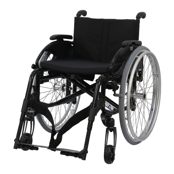
- Page 1 Lightweight wheelchairs Model 2.360 / 2.370 Operating manual W e m o v e p e o p l e .
-
Page 2: Table Of Contents
Indications Acceptance Specifications Wheelchair folding/unfolding/carrying Adjustment Reinstallment Life span Overview Model 2.370 Overview Model 2.360 Brake Pressure brake - user Locking the brakes Releasing the brakes Service brake Butterfly brake - user Locking the brakes Releasing the brakes Service brake... - Page 3 Attaching the calf belt Length adjustment of the calf belt Lower leg support, model 2.370 Footplates Footboard Lower leg support, model 2.360 Footboard Upper leg support, model 2.370, Turning the leg supports to the side Swivelling in the leg supports...
- Page 4 Data according to ISO for model 2.370 Smart S Further technical data for model 2.370 Smart S Data according to ISO for model 2.360 Smart F Further technical data for model 2.360 Smart F Meaning of the symbols on the washing instruction...
- Page 5 Inspection certificate Warranty / Guarantee Warrantee / Guarantee section Inspection certificate for transfer Notes...
-
Page 6: Meaning Of The Applied Markers
This operating manual applies to the follow- Safety instructions with a coloured back- ing models: ground are mandatory and need to be Model 2.360 (slanted front section) observed under any circumstance! Model 2.370 (straight front section) ☞ This symbol indicates tips and recom-... -
Page 7: Specifications
SPECIFICATIONS ☞ The wheelchair is a vehicle and not a carrying device. The wheelchair was developed for adults. Only apply the wheelchair within the The wheelchair solely serves to transport scope of the specifications and limitation one person in the seat and not as a hauling described in chapter Technical data on aid, transporter or similar. -
Page 8: Adjustment
ADJUSTMENT ☞ The indicated lifespan does not consti- tute additional guarantee. Always have adaptation and adjustment work carried out by a specialist dealer. The wheelchair offers manifold adjustment possibilities to individual vital statistics. The wheelchair should be adapted to your needs by a specialist dealer before the first use. -
Page 9: Overview
OVERVIEW Model 2.370 The overview shows, representative for all models, the most important components of the wheelchair. Pos. Description (1) Push handle (8) Steering wheel (2) Back support (9) Type plate (3) Arm support (10) Driving wheel (4) Clothes guard (11) Brake lever –... -
Page 10: Overview
OVERVIEW Model 2.360 The overview shows, representative for all models, the most important components of the wheelchair. Pos. Description (1) Push handle (8) Steering wheel (2) Back support (9) Brake lever – pressure brake (3) Clothes guard (10) Driving wheel... -
Page 11: Brake
BRAKE Arrange an immediate repair of the brakes by your specialist workshop if the braking performance reduces. Wheelchairs with PU-tyres should be stored safely without activated pressure brakes in case of longer standing periods. By locking the brakes with the brake lever (1), the wheelchair is secured against rolling away unintentionally (parking brake). -
Page 12: Butterfly Brake - User
Butterfly brake - user Locking the brakes To secure the wheelchair against any un- intentional rolling, swivel both brake levers outward all the way [2]. ☞ It should not be possible to push the wheelchair forward when both brakes are locked. Releasing the brakes Swivel both brake levers inward all the way [1]. -
Page 13: Drum Brake For Accompanying Persons
Drum brake for accompanying persons Model 2.370 The drum brake is activated by the accom- panying person through the brake levers [1]. Function as operating brakes Use both brake levers evenly and only light- ly in order to achieve a controlled decelera- tion of the wheelchair. -
Page 14: Leg Supports
LEG SUPPORTS Before any actions on the leg supports the wheelchair is to be secured against unintentional rolling motions. ☞ Therefore observe chapter Brake on page 11. Calf belt model 2.370, Do not drive without the calf belt. – Dan- ger of accidents. -
Page 15: Calf Belt Model 2.360
Calf belt model 2.360, Do not drive without the calf belt. – Dan- ger of accidents. The removable calf belt (1) prevents the feet from sliding off the back of the footboard. ☞ The calf belt must be removed in order to swivel away the leg supports. -
Page 16: Lower Leg Support, Model 2.370
Lower leg support, model 2.370 The footplates, resp. footboard needs to be folded up before entry or exit [1]. ☞ Check the locking points! – Remove both feet from the footplates. – Remove lower calf belt, if present. ☞ Therefore observe chapter Calf belt model 2.370, on page 14. -
Page 17: Lower Leg Support, Model 2.360
Lower leg support, model 2.360 The footplates, resp. footboard needs to be folded up before entry or exit [1]. ☞ Check the locking points! – Remove both feet from the footplates. – Remove lower calf belt, if present. ☞ Therefore observe chapter Calf belt model 2.370, on page 14. -
Page 18: Upper Leg Support, Model 2.370
Upper leg support, model 2.370, The upper leg support with an inserted lower leg support is termed leg support. Turning the leg supports to the side Leg supports turned to the side are re- leased automatically and can easily come off. -
Page 19: Swivelling In The Leg Supports
Swivelling in the leg supports For inward swivelling, let the leg supports swivel forward until the lock audibly engag- es [1]. ☞ After audibly swivelling the leg sup- ports inward check the respective lock- ing device. ☞ Afterwards observe chapter Low- er leg support, model 2.370 on page 16. -
Page 20: Removing The Leg Supports
Removing the leg supports For easy transfer into and out of the wheel- chair as well as a reduced wheelchair length (important for transport) the leg supports can be removed [1]. ☞ Remove the calf belt before swivelling away the leg supports. ☞... -
Page 21: Mechanically Height-Adjustable Leg Supports
Mechanically height-adjustable leg supports Never put the free hand into the adjust- ment mechanism. Have the leg support secured by an accompanying person against unintentionally falling down. Do not let the leg support drop on its own weight. – Danger of injury! Lifting/lowering the leg support Before lifting/lowering relieve the leg sup- port by an accompanying person by slightly... -
Page 22: Arm Supports
ARM SUPPORTS Do not use the arm supports to lift or car- ry the wheelchair. Do not drive without the arm supports. No not grab between the frame and arm support. – Danger of squashing! When the wheelchair is being pushed by an attendant the user is to place his hands onto the arm cushions or in his lap and not at the sides between body and... -
Page 23: Inserting The Arm Support
Inserting the arm support (Model 2.370) First insert the arm support from the top into the guide tube behind the seat surface [1]. Then swivel the arm support down until the locking device audibly engages (2). ☞ The tube of the back support must lie in the guide groove on the arm support (3). -
Page 24: Swivelling Up The Arm Support
Swivelling up the arm support (Model 2.370) For transfer out of/into the wheelchair the arm support can be swivelled upward [1] as well as folded behind the back support [2]. Release the locking device (3) first before swivelling up the arm support. Afterwards swivel the armsupport upward [1] and if needed fold it behind the back support [2]. -
Page 25: Clothes Guard
CLOTHES GUARD Do not grab hold of the clothes guard [1] +[2] to lift or carry the wheelchair. Do not drive without the clothes guard! No not grab between the frame and clothes guard. – Danger of squashing! When being pushed in the wheelchair by the accompanying person the user has to keep his hands on the arm supports or in his lap and not at the sides between body... -
Page 26: Push Bar
PUSH BAR Before any actions on the push bar the wheelchair is to be secured against unin- tentional rolling motions. – View chapter Brake on page 11. The removable push bar connects the two back support tubes at the pushing handles [1], serves to push the wheelchair and at the same time is the bracket for the head sup- port. -
Page 27: Push Handles
PUSH HANDLES The height adjustable push handles are about 20 cm continuously height adjusta- ble and secured against being pulled out [1]. Push handles with clamping device ☞ In doing so, hold onto the push handle that is to be adjusted with one hand. ☞... -
Page 28: Wheels
WHEELS Drive wheels After inserting the drive wheel the locking button (2) must stick a couple of millime- tres out of the wheel nut. The drive wheels are supported on a quick release axle [1] and can be removed resp. at- tached without tools. -
Page 29: Support Castors
SUPPORT CASTORS Support castors do not provide sufficient protection against tipping over in certain situations. The support castors [1] serve to raise the tilting stability and can be swivelled inward underneath the seat (2). ☞ Depending on the version the support castors can be attached singly or as a pair. -
Page 30: Head Support
HEAD SUPPORT A headrest mounted to the wheelchair serves as a support for the posture of the head, not as a transport security. The upper edge of the adjustable head sup- port [1] should always be close to the back of the head at about eye level. -
Page 31: Retaining Strap
RETAINING STRAP Make sure that no objects are trapped be- tween belt and the body! The retaining strap is not part of the re- taining system for the wheelchair and/or the driver during transport in motor vehi- cles. The retaining strap [3] is screwed from the back onto the respective back support tube. -
Page 32: Basic Safety Information
BASIC SAFETY ing person for driving slopes of more than 1% tilt. INFORMATION ☞ This low gradient value is valid for per- sons that are not able to effect even Accompanying person the smallest centre of gravity change by changing the position of their upper The accompanying person must be made body. -
Page 33: Crossing Obstacles
must compensate for this drift by a coun- miliar with the danger situation and firmly ter-steering guide the wheelchair. ☞ The helpers may only hold (without lift- Crossing obstacles ing) the wheelchair with the push han- dles and the side frame. After overcoming obstacles, the previous- ly removed support castors need to be Existing support castors are to be removed,... -
Page 34: Transport Of People Inside A Motor Vehicle
With limited visibility and especially in the ☞ Observe the guideline < Safety with dark we recommend to mount active light- Meyra-wheelchairs, also during transport ing equipment and to turn it on in order to in motor vehicles >! – This document see better and be seen. -
Page 35: Cleaning
Koch Institute can be found under: found in the < Infozentrum > on our website: < http://www.rki.de >. < www.meyra.com >. ☞ During the use of disinfectants it can happen that surfaces might be affect- ed in such a fashion that the long term functionality of parts can be limited. -
Page 36: Disposal
DISPOSAL The disposal must comply with the respec- tive national law. Please enquire about local disposal arrange- ments at your municipal authority. MAINTENANCE An incorrect or neglected cleaning and maintenance of the wheelchair results in a limitation of the product liability. Maintenance The following maintenance Instruction gives you a guide for carrying out the main-... -
Page 37: Maintenance Schedule
Maintenance schedule WHEN WHAT REMARK Before starting out General Carry out test yourself or with a helper. Test for faultless operation. Before starting out Test brakes for fault- Carry out test yourself or less operation with a helper. The locked wheels should Activate brake lever to the not be able to turn un- limit. - Page 38 WHEN WHAT REMARK Every 2 weeks Check air pressure of Carry out test yourself or (depending on distance the tyres with a helper. covered) Use a tyre gauge. Tyre filling pressure: ☞ View Tyre pressure of pneumatic tyres page 39. Every 8 weeks Check tyre profile Carry out visual check...
-
Page 39: Technical Data
TECHNICAL DATA Tyre pressure of pneumatic tyres Maximum tyre pressure is printed on the All data given in the < Technical data > refers tyres on each side. to the standard version. Full tyre pressure – steering wheel The overall length depends on the position and size of the drive wheels. -
Page 40: Data According To Iso For Model 2.370 Smart S
Data according to ISO for model 2.370 Smart S Overall length with leg support 880 mm 1030 mm Overall width 500 mm 720 mm Overall dimensions 10.5 kg User weight (incl. additional load) 150 kg Weight of the heaviest part 6.5 kg 9.5 kg Actual seat depth... -
Page 41: Further Technical Data For Model 2.370 Smart S
Further technical data for model 2.370 Smart S Length without leg support 680 mm 820 mm Overall height 700 mm 1050 mm Seat cushion thickness 30 mm 60 mm Length without leg supports, drive wheels (Support castors are removed or swivelled under- 530 mm 670 mm neath the seat) -
Page 42: Data According To Iso For Model 2.360 Smart F
Data according to ISO for model 2.360 Smart F Overall length with leg support 880 mm 1030 mm Overall width 500 mm 720 mm Overall dimensions 9.5 kg User weight (incl. additional load) 150 kg Weight of the heaviest part 7.4 kg... -
Page 43: Further Technical Data For Model 2.360 Smart F
Further technical data for model 2.360 Smart F Length without leg support 800 mm 950 mm Overall height 700 mm 1050 mm Seat cushion thickness 30 mm 60 mm Length without leg supports, drive wheels (Support castors are removed or swivelled under-... -
Page 44: Meaning Of The Symbols On The Washing Instruction
Meaning of the symbols on the washing instruction (the symbols correspond to European standard) Wash as delicates with the indicated maximum temperature in °C Wash as regular laundry with the indicated maximum temperature in °C Do not bleach Not suited for the dryer Do not iron Do not dry-clean... -
Page 45: Meaning Of The Labels On The Wheelchair
Meaning of the labels on the wheelchair Attention! Read the operating manuals and other provided documen- tation. Do not lift the wheelchair at the arm supports or leg sup- ports. Removable parts are not suitable for carrying. Attention Readjust the brakes. Attention Increased danger of tilting when on inclinations / slopes, es- pecially in combination with short wheel base... -
Page 46: Meaning Of The Symbols On The Type Plate
Meaning of the symbols on the type plate Manufacturer Order number Serial number Production date (Year – Calendar week) Permitted user weight max. permissible total weight Permitted axle weights Max. permissible rising gradient Max. permissible falling gradient Permitted maximum speed The product is approved as a seat within a motor vehicle The product is not approved as a seat within a motor vehicle. -
Page 47: Inspection Certificate
INSPECTION CERTIFICATE Recommended safety inspection 1st year (at least every 12 months) Vehicle data: Stamp of specialist dealer: Model: Signature: Delivery note no.: Place, date: Serial-no.(SN): Next safety inspection in 12 months Date: Recommended safety inspection 3rd year Recommended safety inspection 2nd year (at least every 12 months) (at least every 12 months) Stamp of specialist dealer:... -
Page 48: Warranty / Guarantee
WARRANTY / GUARANTEE norm specifications cannot be declared as warranty or guarantee claims. We accept legal liability for this product Attention: within the scope of or general terms and Failure to observe the instructions in conditions and warranty and in certain cas- the operating manual, improperly car- es other verbal resp. -
Page 49: Warrantee / Guarantee Section
Warrantee / Guarantee section Please fill out! Copy if necessary and send the copy to the specialist dealer. Warranty / Guarantee Model designation: Delivery note no.: SN (view type plate): Date of delivery: Stamp of the specialist dealer: Inspection certificate for transfer Vehicle data: Serial-no.(SN): Stamp of specialist dealer:... -
Page 50: Notes
NOTES... - Page 51 NOTES...
- Page 52 Your specialist dealer MEYRA GmbH Meyra-Ring 2 D-32689 Kalletal-Kalldorf +49 5733 922 - 311 +49 5733 922 - 9311 info@meyra.de www.meyra.de MEYRA 205 345 001 (Status: 2017-07) All technical modifications reserved.
Need help?
Do you have a question about the 2.360 and is the answer not in the manual?
Questions and answers