
Related Manuals for Meyra 1.594


Summary of Contents for Meyra 1.594
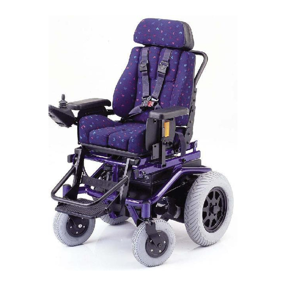
- Page 1 The Motivation. L CTRIC WH LCHAIR HAMP, ODEL 1.594 HAMP LIFT ODEL 1.594-27 HAMPI, ODEL 1.594-603 OPERATING MANUAL...
-
Page 2: Table Of Contents
Assembly ....................6 Specifications/ utilisation ................ 7 Safety informations ................. 7 Overview ....................8 hamp, Model 1.594 – Model 1.594-27 ............8 hampi, Model 1.594–603 ................9 Statutory regulations ................10 Legal requirements for Germany ..............10 Electronic wheelchairs up to 6 km/h ............10 Electronic wheelchairs more than 6 km/h .......... - Page 3 Leg supports ................... 18 Folding up the footplates ............... 18 Turning the leg supports to the side ............19 Removing the leg supports ..............20 Adjusting the length of the leg supports ..........21 Electrically height-adjustable leg support, code 86 ........22 Height adjustment ...................
- Page 4 Push mode ....................40 Push mode ..................... 40 Drive mode ....................40 Options ....................41 Seat belt ......................41 losing the seatbelt ................. 42 Opening the seatbelt................42 Adjustment of belt length ..............42 Push handle for attendant ................43 Adjusting the position of the push bar ..........
- Page 5 Special features of Champi, model 1.594-603 ........57 4-way seatbelt ....................57 Adjustments ....................58 Leg support ....................63 Arm support ode 79 ................... 64 Transport of objects ..................65 Service ..................... 66 Maintenance ....................66 are........................ 66 Upholstery and covers ................66 Plastic parts ....................
-
Page 6: Ntroduction
All MEYRA products are checked for hamp, model 1.594 and model 1.594- faults in the factory and packed in spe- 27 as well as hampi, model 1.594– cial boxes. 603 fulfil the desires for mobility and more independence with the proven... -
Page 7: Specifications/ Utilisation
B’ as per the EN12184 standard. – Detachable parts like e.g. arm The hamp, model 1.594 and model supports and leg supports have to 1.594-27 as well as hampi, model be used properly To guarantee 1.594–603 are only conditionally suit-... -
Page 8: Overview
OVERVIEW HAMP, MODEL 1.594 – MODEL 1.594-27 The model shown in Fig. 1 and 2 is the standard version. All deviations are specified separately in this operating manual. Pos. Description 1 Push bar 2 Back cushion 3 Side part with arm support... -
Page 9: Hampi, Model 1.594–603
OVERVIEW HAMPI, MODEL 1.594–603 The model shown in fig. 1a and 2a is the standard version. All deviations are specified separately in this operating manual. Pos. Description 1 Push bar 2 Headrest 3 Back support 4 Side part with arm support... -
Page 10: Statutory Regulations
STATUTORY REGULA- TIONS Electronic wheelchairs up to 6 km/h A liability insurance is only mandato- Please comply with the legal require- ry (in Germany) for an electronic ments of the country in which the wheelchair with a speed in excess of wheelchair is used. -
Page 11: E Regulations
E REGULATIONS ontact your insurance office first. There you will receive an insurance li- cence plate (moped plate), which is to Note: This vehicle corresponds to the re- be attached to the rear panel with two spective demands of the E -direc- screws. -
Page 12: Driving
DRIVING SAFETY INFORMATIONS Do not touch the ON/OFF button Drive especially carefully during your while driving. Pressing the key will first journey! then switch off the electric wheel- Bearing this in mind, set the pre-se- chair and cause it to stop immedi- lectable final speed to the lowest set- ately. -
Page 13: First Driving Exercises
FIRST DRIVING EXER ISES BRAKING THE WHEEL HAIR A low maximum speed must be pre- The wheelchair stops when you re- selected on the control unit for the lease the driving- and steering lever. initial driving practice. Make yourself Always ensure an adequate braking familiar with the driving behaviour of distance when applying the wheel- the electric wheelchair in small steps. -
Page 14: Emergency Off
BRAKES If drive mode is switched off (brake release lever in the „push“ position) the wheelchair cannot be operated The brakes are one of the most im- and braked via the joystick! In this portant safety features of a wheel- event, use the brake release lever chair. -
Page 15: Brake Release Lever
BRAKE RELEASE LEVER Locking the brake Push the brake release lever forward as far as it will go (fig. 3). Caution: It is impossible to push the wheel- chair when in drive mode. The brake performance reduces with the brake pads are worn. If the wheelchair demonstrates an uneven or impaired braking effect, take it immediately to your specialist... -
Page 16: Preparing The Wheelchair For Operation
PREPARING THE WHEEL- CHAIR FOR OPERATION Follow the instructions below in the stated order. SHIFT TO DRIVE MODE Push the brake release lever forward as far as it will go (fig. 3). Caution: Do not switch to push mode when the wheelchair is in operation! nsert the battery fuse (main fuse) -
Page 17: Switching The Operating Module On
SWIT HING THE OPERAT- ING MODULE ON Press the ON/OFF-key on the key field of the control panel (fig. 7). (Observe the brochure < operating modules >). Note: – Only transfer to and from the wheelchair when the wheelchair is switched off and the brake release lever has been placed into the for- ward position! -
Page 18: Leg Supports
LEG SUPPORTS Caution: The leg supports are adjustable and detachable parts and are not suitable as a means of lifting up or carrying the wheelchair (See warn- ing on the arm supports). Folding up the footplates Benefits: – Easy transfer into and out of the wheelchair. -
Page 19: Turning The Leg Supports To The Side
Turning the leg supports to the side Benefits: – Easy transfer into and out of the wheelchair. – Leg region free, no stumbling. – lose access to cupboards possible. – Reduced length of the wheelchair, – for storing the wheelchair. Handling: –... -
Page 20: Removing The Leg Supports
Removing the leg supports Benefits: – Easy transfer into and out of the wheelchair. – Foot and side areas are free, no stumbling. – Reduced length of the wheelchair – important for storing wheelchair. Handling: – Switch off the wheelchair and move the brake release lever to the “drive”... -
Page 21: Adjusting The Length Of The Leg Supports
Adjusting the length of the leg supports The leg supports can be adjusted via a telescopic tube. Benefits: – Individual adjustment of the leg supports to the length of your low- er leg. Handling: Tools: 1x hexagonal stud wrench (width 4 –... -
Page 22: Electrically Height-Adjustable Leg Support, Code 86
ELE TRI ALLY HEIGHT- ADJUSTABLE LEG SUPPORT, ODE 86 (Fig. 14.1) The electrically adjustable leg support has an automatic length alignment and automatic electrical contact upon being mounted. Caution: Do not reach into the adjustment mechanism. – Danger of crushing! Height adjustment For the height adjustment of the leg supports (fig. -
Page 23: Adjusting The Length Of The Leg Supports
Adjusting the length of the leg supports The leg supports can be adjusted via a telescopic tube. Benefits: – Individual adjustment of the leg supports to the length of your low- er leg. Handling: Tools: 1x hexagonal stud wrench (width 4 –... -
Page 24: Dismantling The Electrical Leg Supports
Dismantling the electrical leg supports Benefits: – Easy transfer into and out of the wheelchair. – Foot and side areas are free, no stumbling. – Reduced length of the wheelchair – important for storing wheelchair. Handling: – Switch off the wheelchair and move the brake release lever to the “drive”... -
Page 25: Attaching The Electrical Leg Supports
Attaching the electrical leg supports Handling: – Switch off the wheelchair and move the brake release lever to the “drive” position. – This prevents the wheelchair from rolling away accidentally. Assembly of the electric leg support is done in reverse order to the removal of the electric leg supports. -
Page 26: Arm Supports
AR SUPPORTS The arm supports generally have pad- ded arm supports. They are lockable and detachable, as well as adjustable in height (fig. 14.8). Benefits: – Adjusting screws prevent the arm supports from inadvertently sliding out. – Mudguard. – Wind protection. –... -
Page 27: Removing The Arm Supports
REMOVING THE ARM SUP- PORTS – Switch off the wheelchair and move the brake release lever to the “drive” position. – This prevents the wheelchair from rolling away accidentally. – Remove the arm support in an up- wards direction (fig. 15). – This is carried out by loosening the rele- vant adjusting screw (A, fig. -
Page 28: Remove The Operating Module
Remove the operating module – To remove the operating module loosen the clamping screw (B, fig. 16.1) and pull the operating mod- ule out to the front. – For safe transport of the operat- ing module it can be inserted into the holder of the arm support (fig. -
Page 29: Mounting The Arm Supports
Mounting the arm supports – Switch off the wheelchair. Move the brake release lever into the “drive” position. – This prevents the wheelchair from rolling away accidentally. – Insert the arm supports into their guides (up to the end stop) and then tighten the adjusting screws (A, fig. -
Page 30: Seat
SEAT The cushion can be removed down for maintenance and repair work (fig. 18). REMOVING THE SEAT USHION – Switch off the wheelchair. Move the brake release lever into the “drive” position. – This prevents the wheelchair from rolling away accidentally. -
Page 31: Placing The Seat Cushion
PLA ING THE SEAT USH- Note: Move the brake release lever into the “drive” position. – This pre- vents the wheelchair from rolling away accidentally. – Place the seat cushion onto the guide rails (A, fig. 21) and push it back (fig. -
Page 32: Adjustment Of Seat Width
ADJUSTMENT OF SEAT WIDTH Note: Switch off the wheelchair. Move the brake release lever into the “drive” position. – This prevents the wheelchair from rolling away accidentally. Push the arm support outwards/ inwards – Loosen the clamping screw (A, fig. 24) of the clamp guide. -
Page 33: Adjusting The Seat Depth
ADJUSTING THE SEAT DEPTH The seat depth can be adjusted from 39-48 cm. Note: Switch off the wheelchair. Move the brake release lever into the “drive” position. – This prevents the wheelchair from rolling away accidentally. To remove the seat cushion observe the chapter <... -
Page 34: Manual Seat Adjustment
MANUAL SEAT ADJUST- MENT Angle adjustment of the seat The seat can be adjusted in angle in 4 positions (max. 60 mm) to the rear (fig. 25). Caution: Before adjustment secure the frame tube (A, fig. 25) with one hand to prevent it from falling down. -
Page 35: Electrical Seat Adjustment
The front edge of the seat swivels The front edge of the seat swivels (max. 30°) up (fig. 27.1). down. Caution: ( hamp, Model 1.594 and Model 1.594-27) A negative seat inclination reduc- es the distance of the footplates to the driving surface. – Accordingly the max. -
Page 36: Rising Aid
Rising aid Only in combination with hamp, model 1.594 and model 1.594-27. The rising aid is achieved by a nega- tive seat inclination setting to max. 10° and therefore makes transfer out of / into the wheelchair easier. Attention: For transfer out of / into the wheel- 27.2... -
Page 37: Back Support
BACK SUPPORT The back support can be inclined and removed. REMOVING THE BA K – Switch off the wheelchair. Move the brake release lever into the “drive” position. – This prevents the wheelchair from rolling away accidentally. – Screw out the securing screws un- til the back support is released (A, fig. -
Page 38: Adjusting The Angle Of The Back Support
ADJUSTING THE ANGLE OF THE BA K SUPPORT Mechanical back support ad- justment – Switch off the wheelchair. Move the brake release lever into the “drive” position. – This prevents the wheelchair from rolling away accidentally. – Slacken the screw connection (A, fig. -
Page 39: Electrical Back Support Adjustment
Electrical back support adjust- ment (Option) The electrically adjustable back sup- port can be adjusted over the operat- ing module. – Pressure relief for buttocks muscles (decubitus prophylaxis). – Relief for the spinal column. 3 .2 – Fatigue-free sitting. For electric angle adjustment of the Adjusting the back support back support (fig. -
Page 40: Push Mode
PUSH ODE The wheelchair can also be switched to push mode. The electronic wheelchair has a con- siderably higher weight than conven- tional wheelchairs (motor, batteries). This means that higher pushing and steering force are necessary. Caution: Only push the wheelchair on level surfaces. -
Page 41: Options
OPTIONS Options are not a part of the stand- ard scope of supply. Note: Options from other companies can cause malfunctions. SEAT BELT Code 833 (Fig. 34) The seatbelt serves to strap in a per- son sitting in the wheelchair. Benefits: –... -
Page 42: Losing The Seatbelt
Closing the seatbelt Pull both belt halves to the front and slide the catch halves together so that they latch together (fig. 34.1). – Then carry out a pull test. Caution: Make sure that no objects are trapped between belt and the body! –... -
Page 43: Push Handle For Attendant
PUSH HANDLE FOR AT- TENDANT Note: Only in combination with the re- spective attendant control. The removable push handle (fig. 35) for attachment of an attendant con- trol (fig. 35.2) is swivel proof, height adjustable and removable. Attention: Observe the changed wheelchair dimensions, especially while turn- ing or driving backwards. -
Page 44: Operating Module For Accompanying Person
OPERATING MODULE FOR A OMPANYING PERSON The operating module for the attend- ant (fig. 35.2) switched the operating module of the user off. Attention: Observe brochure < operating module >! Observe the changed wheelchair 35.2 dimensions, especially while turn- ing or driving backwards. Positioning the operating mod- –... -
Page 45: Headrest
HEADREST The headrest (fig. 36) is swivel proof, height adjustable and removable. Attention: We recommend the fitting of two rear-view mirrors for driving with a headrest. Adjustment of the headrest – Switch off the wheelchair and move the brake release lever to the “drive”... -
Page 46: Seat Height Adjustment
SEAT HEIGHT ADJUSTMENT Only in combination with hamp, model 1.594. The technical data is located under hamp Lift, model 1.594-27. The seat height adjustment (fig. 36.1) raises the seat height continuously up to 30 cm. Note: The seat height adjustment is not designed for short subsequent lift- ing motions. -
Page 47: Safety Informations
Safety informations Before first use the specialist deal- er should conduct an orientation! The maximum loading for the seat height adjustment is limited to 130 Attention: Only conduct seat height adjust- ments on firm, level surfaces with- out seat adjustments while driving (fig. -
Page 48: User Instructions Before Seat Height Adjustment
User instructions before seat height adjustment The seat height adjustment may only be used with fastened safety belt! For a seat height adjustment suffi- cient free space must be available above the wheelchair. – Danger of accidents e.g. through door frames, lamps (fig. -
Page 49: User Instructions After Seat Height Adjustment
User instructions after seat height adjustment Due to the limited field of vision special caution is required when driving with the wheelchair (fig. 36.5)! Pay attention to hanging objects (fig. 36.6)! Do not lean the upper body be- yond the seating contour! – Dan- ger of overturning! With completely or partially raised seat height adjustment the accel-... -
Page 50: Loading And Transportation
LOADING AND TRANS- PORTATION Safety informations For the transport in vehicles, you must leave the wheelchair and sit in a suit- able seat in the vehicle. – The wheel- chair is not designed to withstand the forces which are generated in acci- dents, which exposes the user to con- siderable risks. -
Page 51: Transport Security
Transport security arry out the following steps when the wheelchair is located in the trans- port vehicle: – Switch off the wheelchair. – Put the operating module in a safe place or replace it on the wheel- chair. – Stow all disassembled wheelchair parts in a secure and protected way. -
Page 52: Safety Informations
Safety informations Note: Suitable fixing points can usually Loose object are to be stored se- be found in the car and in the ve- curely. hicle operating manual. Before transporting the wheel- chair, ask your car dealer how to secure it without risk to the exist- ing fixtures or other safety fittings! Attention: Make sure that the operating mod-... -
Page 53: Ramps And Lifting Equipment
RAMPS AND LIFTING EQUIPMENT When the wheelchair is loaded with the help of ramps or lifting platforms, the following safety information are to be observed: The brochure < Safety informa- tions – electronic wheelchairs > The operating manual for the transport vehicle. -
Page 54: Special Safety Informations
Only approved ramps or lifting Special safety informations equipments may be used. For safety reasons, the wheelchair must be unloaded (without bag- Attention: gage and without user) during its The loading capacity per ramp or loading into a car or when a split lifting equipment must be for the ramp is used. -
Page 55: Transport In Handicapped Transport Automobile
TRANSPORT IN HANDI- The power-knot-system is a firm, ret- APPED TRANSPORT AUTO- rofitable element on the wheelchair, MOBILE on which the PRS and WRS merge. These requirements are fulfilled by a Note: 4-point-system that consists of 2 front For transport in vehicles we recom- standardized latches for spanning re- mend to leave the wheelchair and actor and 2 rear standardized latches... -
Page 56: Product Liability Instructions
Safety informations Note: The headrest on the wheelchair When transporting a person, make serves as a support for the posture sure that there are no objects of the head, not as a transport se- jammed underneath the straps! – curity. Therefore a handicapped Thus you avoid painful pressure transport vehicle-firm headrest is points... -
Page 57: Special Features Of Champi, Model 1.594-603
SPECIAL FEATURES OF CHA PI, ODEL 1.594- 4-WAY SEATBELT Caution: Never drive without a fastened - point safety belt (fig. 001). Note: The strap may not press onto any objects. For safety reasons the clothes pockets are to be emptied before fastening the seatbelt. -
Page 58: Adjustments
SPECIAL FEATURES OF CHA PI, ODEL 1.594- ADJUSTMENTS Adjusting the back support angle The back support can be inclined up to 45° by turning the handwheel (fig. À 004/ ) anticlockwise. To raise the back support the hand À wheel (fig. 004/ ) is to be turned clockwise. - Page 59 SPECIAL FEATURES OF CHA PI, ODEL 1.594- Adjusting the seat depth Note: Prior to adjusting the seat depth the seat has to be swivelled up- ward to the front. – For this pull the rope of the seat À lock (fig. 007/ ) in the centre.
- Page 60 SPECIAL FEATURES OF CHA PI, ODEL 1.594- Back cushion After removing the back cushion (fig. 009) the back height and side cush- ions can be adjusted. – To remove the back cushion, first open the velcro strap at the back and pull it to the front (fig.
- Page 61 SPECIAL FEATURES OF CHA PI, ODEL 1.594- Seat cushion After removing the seat cushion (fig. 013) the seat side cushions can be ad- justed. – To remove the seat cushion you previously need to open the velcro straps of the leg latches in the front underneath the seat plate (fig.
- Page 62 SPECIAL FEATURES OF CHA PI, ODEL 1.594- Backrest height adjustment After disassembly of the screwed con- À nections on both sides (fig. 017/ ) the back plate can be repositioned accord- ingly in the holes. After repositioning the screwed connections on both sides are to be reassembled.
-
Page 63: Leg Support
SPECIAL FEATURES OF CHA PI, ODEL 1.594- Adjustment of seat width The seat width is adjustable through even adjustment of the arm supports after loosening the respective clamp- À ing screw (fig. 020/ Note: Maximally push the arm support outward up to the marker. -
Page 64: Arm Support Ode 79
SPECIAL FEATURES OF CHA PI, ODEL 1.594- Adjusting the length of the thigh After loosening the opposite clamp- À ing screws (fig. 023/ ) the leg sup- port can be adjusted according to the length of the thigh (fig. 024). -
Page 65: Transport Of Objects
SPECIAL FEATURES OF CHA PI, ODEL 1.594- Horizontal adjustment of the À operating module Loosen the hand wheel (fig. 027/ After the adjustment retighten hand À wheel securely. Swivelling away the operating module Press the operating module outward over the pressure point and swivel it toward the back (fig. -
Page 66: Service
SERVICE Plastic parts The plastic panels and parts are made MAINTENAN E of high-quality plastic. Take care of these by means of standard plastics Like any other technical product, your cleaning agents. Always observe the wheelchair also requires maintenance. specific product information. The following maintenance instruc- tions describe in table form the work that has to be carried out so that you... -
Page 67: Desinfection
DESINFE TION USTOMER SERVI E For desinfection you should use In case you have any questions or need agents on a water basis such as Terra- help please contact your specialist lin, Quartamon Med or Sagrotan Orig- dealer who can assume counselling, inal oncentrate. -
Page 68: Spare Parts
SPARE PARTS Spare parts can only be ordered from authorised dealers. Use only original spare parts for repairs! In order to ensure the correct deliv- ery of a spare part, always quote the corresponding frame number of the wheelchair! If any modifications have been made to the wheelchair, the specialized dealer is required to enclose the ap- propriate code no. -
Page 69: Batteries
BATTERIES Battery instructions for storage Before storage, for example before a Charging the batteries winter pause, the following instruc- – before long tours tions are to be observed: – after long periods of disuse ompletely charge the batteries. – when the battery indication light Pull off the drive key (if available). - Page 70 Charging procedure Do not recharge the batteries in a damp room or enclosed space. – The charging process can produce toxic fumes. Ensure that the room is well- ventilated! – Switch off the wheelchair. Move the brake release lever into the “drive”...
- Page 71 Maintenance the batteries Always remove the main fuse before working on the batteries or electrical/ electronic components (fig. 42)! Caution: Do not touch the battery terminals with tools, cable ends or other metallic items. – Risk of short cir- cuit and explosion! Avoid naked flames and sparks in the vicinity of the batteries.
- Page 72 Maintenance of lead-acid bat- teries Lead-acid batteries have visible seal- ing plugs. A regular battery mainte- nance contributes to the full utilisa- tion of the service life of the batter- ies. Caution: Battery acid is caustic! In event of acid droplets on the skin, in the eyes or on clothing, rinse immediately under running water.
- Page 73 Checking the acid level First charge discharged batteries and, if necessary, then top up with distilled water. The battery acid level falls due to evaporation of water, especially dur- ing high ambient temperature. The acid level is correct when it is –...
- Page 74 Replacing the batteries Batteries should be replaced by your specialist workshop only because it is aware of the associated risks. Batter- ies can explode if they come into con- tact with sparks, e.g. due to a short circuit of the battery terminals. Caution: Defective batteries should be prop- erly disposed of!
- Page 75 External seating system: 4. Take off the arm supports (fig. 51.1) Note: Hereto observe chapter < Arm sup- ports >. 5. Pull the rope for the seat lock (fig. 51.2). 6. Swivel the seat upward to the front (fig. 51.3). Note: heck the seat lock after swivelling it back inward!
- Page 76 CAN-Bus-version: Depending on equipment continue with the respective position as follows on wheelchairs with the AN-bus op- erating module (fig. 51.5). 8. Open the velcro fastener of the spanning belt. 9. Lift off the battery cover (fig. 51.6). 10.Remove the wing nuts (A, fig. 5 .5 51.6).
- Page 77 Electrical back support adjustment 4. Remove the seat cushion (fig. 51.9). 5. Pushing the arm supports outward. Therefore observe chapter < Ad- justing the seat width >. 6. Open the velcro fastener of the spanning belt. 7. Lift off the battery cover (fig. 51.10).
- Page 78 Battery removal 1. Wipe the surface of the battery with a dry cloth. 2. Dismantle the battery terminal clips. 3. Raise the carrying handle (fig. 51.13). 4. Remove batteries. Ensure the correct arrangement of the 5 . 3 battery terminals when installing the batteries in the reverse order of the above steps.
-
Page 79: Maintenance Instructions
MAINTENAN E INSTRU TIONS WHEN WHAT REMARK arry out test yourself or Before starting out Brake equipment Test for faultless opera- with a helper. tion. Move the brake release lever to drive mode. It Replacing defective fila- Especially before driv- should now be impossi- ment bulbs view chapter ing in the dark... - Page 80 (depending on frequen- leanness See Repairs. cy of use) General condition Do it yourself or with the aid of a helper. MEYRA recommenda- To be carried out by the Safety inspection tion: authorised dealer. Every 12 months (depending on frequen-...
-
Page 81: Lighting
LIGHTING Switch off the wheelchair and pull out the main fuse (A, fig. 52) before re- placing a defective bulb. Note: If a turn-signal bulb is defective, the remaining one in front blinks at double frequency. Headlight setting The headlights should be set in such a way that the light cone is visible on the road. - Page 82 Replacing a headlight bulb Filament bulb: 24V/3W E10 Tools: Phillips screw driver Removal: – Loosen the fastening screw and re- move the lens cover (fig. 54). – Pull the socket with bulb out of the lens cover. – Unscrew the faulty bulb from the socket (fig.
- Page 83 Front indicator Spherical bulb: 24V/10W BA15s Tools: Phillips screw driver Removal: – Loosen the fastening screw and re- move the lens cover (fig. 56). – Press the faulty spherical bulb slightly inwards, turn and remove from the socket. Mounting: – Insert a new spherical bulb. – Push the side pins (bayonet catch) into the recesses of the bulb holder, press lightly against the spring and...
- Page 84 Rear indicator Spherical bulb: 24V/21W BA15s Tools: Phillips screw driver Removal: – Loosen the fastening screws and remove the lens cover (fig. 57). – Press the faulty spherical bulb slightly inwards, turn and remove from the socket. Mounting: – Insert a new spherical bulb. – Push the side pins (bayonet catch) into the frame, exert slight pressure against the spring and turn until...
- Page 85 Back light Filament bulb: Festoon bulb 24 V/ 5W S8.5 Tools: Phillips screw driver Removal: – Loosen the fastening screws and remove the lens cover (fig. 59). – Press the faulty bulb against a hold- ing frame and remove. Mounting: –...
-
Page 86: Fuses
FUSES Replacing a defective safety fuse Caution: Only replace the safety fuse with a safety fuse of the same type! New safety fuses are available at all petrol stations. If the safety fuse blows again, take the battery to your specialist dealer for repair. -
Page 87: Fault Correction
FAULT ORRE TION If treated properly, your wheelchair will not malfunction. To ensure that your wheelchair gives you many years of service, especially if it is your first electronic wheelchair, we have listed possible faults and remedial action to be taken in the following table. We recommend that an inspection is carried out every 2 years to permit the early recognition and clearance of... - Page 88 Fault Cause Remedy LED display does not The main fuse for the hange the blade-type light up after the battery circuit is defec- electric fuse or insert it wheelchair has been tive (blade-type fuse) or properly. switched on. inserted deep enough.
- Page 89 Overload limiting 40 A min. for 15 sec. min. Blade-type fuses 60.0 A Main fuse Filament bulbs Headlights: Spherical bulb 24V/3W E10 Rear light: Festoon bulb 24V/ 5W S8.5 Front indicator: Spherical bulb 24V/10W BA15s Rear indicator: Spherical bulb 24V/21W BA15s...
-
Page 90: Meaning Of The Labels On The Wheelchair
MEANING OF THE LABELS ON THE WHEEL HAIR Attention! Read the operating manuals and oth- er provided documentation. Do not lift the wheelchair at the arm supports or leg supports. Detachable parts are not suitable for carrying. Drive mode Push mode Grabbing forbidden... -
Page 91: Technical Data
TECHNICAL DATA – frequent acceleration and braking (e.g. in city traffic) – aged, sulphated batteries, Kilometric performance – frequently necessary steering ma- Kilometric performance depends to a noeuvres, large extent on the following factors: – reduced driving speed (especially – battery condition, at walking speed). -
Page 92: Hamp, Model 1.594
Dimensional tolerance ± 1.5 cm, +/-2°. Model: Electric wheelchair: . Champ 1.594 / Champ Lift 1.594-27 / Champi 1.594- Type plate: ........... at the front right on the crossbrace lass of use as per DIN EN 12184: .............. lass B Electrical system: Drive control: ................ - Page 93 Length (without footplates): ..............85 cm Width (without arm supports): ..............64 cm Height (without back support): ..............57 cm hamp Lift 1.594-27: Length (without footplates): ..............88.5 cm Width (without arm supports): ..............64 cm Height (without back support): ..............60 cm hampi 1.594-603:...
- Page 94 Open drive batteries (acid): ..........2 x 12 V 60 Ah (5 h) Max. battery dimensions (LxWxH): ........280 x 180 x 200 mm Permissible battery tilting angle: ..............55° hamp Lift 1.594-27: Sealed drive batteries (gel): ..........2 x 12 V 50 Ah (20 h) (see Kilometric performance): Range Drive batteries (gel) 60 Ah (20h) at 6 km/h: .........
- Page 95 Empty weight (with 60 Ah acid-batteries): ......... approx. 100 kg Transport weight (without back support, arm supports, leg supports):..92 kg Empty weight without batteries: ........... approx. 60 kg hamp Lift 1.594-27: Max. permissible total weight:..............260 kg Permitted axle load front: ................120 kg Permitted axle load rear: ................
-
Page 96: Nspection Certificate
INSPECTION CERTIFICATE ehicle data: Model: Delivery note no.: Vehicle identification No. Recommended safety inspection (at least every 12 months) re-delivery inspection tamp of authorised dealer: tamp of authorised dealer: ignature: ignature: Place, date: Place, date: Next safety inspection in 12 months Next safety inspection in 12 months Date: Date:... - Page 97 Recommended safety inspection Recommended safety inspection (at least every 12 months) (at least every 12 months) tamp of authorised dealer: tamp of authorised dealer: ignature: ignature: Place, date: Place, date: Next safety inspection in 12 months Next safety inspection in 12 months Date: Date: Recommended safety inspection...
-
Page 98: Guarantee
GUARANTEE Damage to surfaces, tyres, damage due to screws and washers which have worked loose or worn out attachment We accept a guaranty for this prod- holes due to frequent assembly and uct according to the legal regulations. dismantling are not covered by this Apart from this we warrant: guarantee. - Page 99 GUARANTEE OUPON Fill in the details! If necessary, copy and return. uarantee Model designation: Delivery note no.: Vehicle ID No. (Fz-I-Nr.) (view type plate): Date of delivery: Stamp of the authorized dealer:...
- Page 100 Stamp of the authorized dealer: The Motivation. MEYRA Wilhelm Meyer GmbH & Co. KG Company address: Meyra-Ring 2 D- 2689 Kalletal-Kalldorf Telephone: +49 (0)57 922 - 11 Fax +49 (0)57 922 - 14 Email: info@meyra.de Internet: http://www.meyra.de Postal address:...
Need help?
Do you have a question about the 1.594 and is the answer not in the manual?
Questions and answers