Meyra 1.610 Operating Manual
Electric wheelchair
Hide thumbs
Also See for 1.610:
- Operating manual (68 pages) ,
- Maintenance and service manual (104 pages) ,
- Operating manual (84 pages)

Related Manuals for Meyra 1.610


Summary of Contents for Meyra 1.610
- Page 1 Electric wheelchair Model 1.610 / 1.611 / 1.612 / 1.613 / 1.615 / 1.616 Operating manual W e m o v e p e o p l e .
-
Page 2: Table Of Contents
Contents Introduction Indications Specifications List of models Acceptance Adjustment Life span Overview Model 1.610 Model 1.611 Model 1.612 Model 1.613 Model 1.615 Model 1.616 Handling the electric wheelchair Securing the electric wheelchair Functional checks Driving Brakes Service brake Braking the wheelchair... - Page 3 Selecting the operation Pre-operation checks Battery charging procedure Positioning the operating module Function description Adjusting the distance to the padded arm support Removing the operating module Inserting the operating module Swivelling the operating module Height adjustment of the operating module Leg supports Calf belt Removing the calf belt...
- Page 4 Back support Folding down the back support Unfolding the back support Adjusting the back support angle Secure positions of the back support Adjustable back Removing the back support upholstery Placing the back support upholstery Electrically adjustable back support Folding down the electrically adjustable back support Unfolding the back support Back support upholstery Secure positions of the back support...
- Page 5 Replacing the fuses Lighting Headlights Fault correction Technical data Kilometric performance Hill climbing ability Model 1.610 / 1.611 Model 1.612 Model 1.613 Model 1.615 Model 1.616 Meaning of the labels on the electric wheelchair Meaning of the symbols on the type plate...
-
Page 6: Introduction
We thank you for the confidence you have placed in our company by choosing an < www.meyra.com >. electric wheelchair from this series. ☞ Contact your specialist dealer when re- With all equipment and their accessories quired. -
Page 7: Indications
If the following indications occur we rec- This operating manual applies to the follow- ommend the application of this mobility ing models: product: Model 1.610 ☞ Walking disability resp. extremely lim- Model 1.611 ited walking ability as part of the ba- Model 1.612 sic need to move around in your own Model 1.613... -
Page 8: Use
☞ We recommend regular medical exams in order to ensure safety for active par- ticipation in traffic. The electric wheelchair, with attached leg supports and arm supports, serves exclu- ☞ Retrospective adjustments should be sively for the conveyance of one sitting per- carried out solely by the specialist deal- son. -
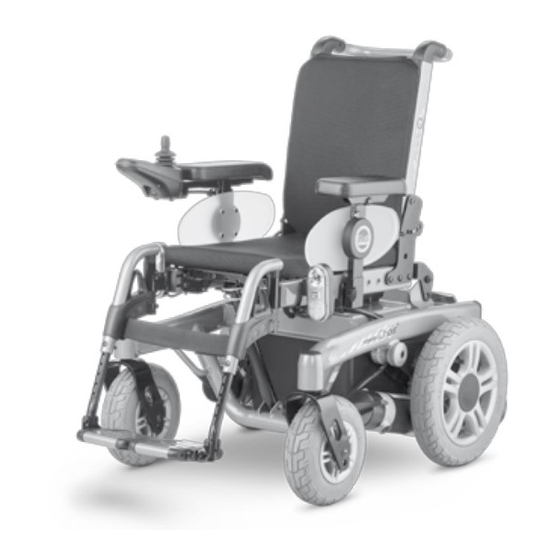
Page 9: Overview
OVERVIEW Model 1.610 The overview shows the most important components and operating devices of the electric wheelchair. Pos. Description (1) Back support (2) Arm support (3) Seat cushion (4) Leg support (5) Calf belt (6) Footplate (7) Steering wheel (8) Driving wheel... -
Page 10: Model 1.611
OVERVIEW Model 1.611 The overview shows the most important components and operating devices of the electric wheelchair. Pos. Description (1) Back support (2) Arm support (3) Seat cushion (4) Leg support (5) Calf belt (6) Footplate (7) Steering wheel (8) Driving wheel (9) Pushing bar (10) Operating module (11) Front lighting... -
Page 11: Model 1.612
OVERVIEW Model 1.612 The overview shows the most important components and operating devices of the electric wheelchair. Pos. Description (1) Back support (2) Arm support (3) Seat cushion (4) Leg support (5) Calf plate (6) Footplate (7) Steering wheel (8) Driving wheel (9) Pushing bar (10) Operating module (11) Front lighting... -
Page 12: Model 1.613
OVERVIEW Model 1.613 The overview shows the most important components and operating devices of the electric wheelchair. Pos. Description (1) Back support (2) Arm support (3) Operating module (4) Front lighting (5) Driving wheel (6) Leg support (7) Support castor (8) Selection lever drive-/push mode (9) Steering wheel (10) Rear lighting... -
Page 13: Model 1.615
OVERVIEW Model 1.615 The overview shows the most important components and operating devices of the electric wheelchair. Pos. Description (1) Back support (2) Arm support (3) Operating module (4) Seat cushion (5) Calf belt (6) Footplate (7) Steering wheel (8) Selection lever drive-/push mode (9) Driving wheel (10) Front lighting (11) Pushing bar... -
Page 14: Model 1.616
OVERVIEW Model 1.616 The overview shows the most important components and operating devices of the electric wheelchair. Pos. Description (1) Back support (2) Arm support (3) Seat cushion (4) Footplate (5) Steering wheel (6) Driving wheel (7) Pushing bar (8) Operating module (9) Selection lever drive-/push mode (10) Support castor (11) Battery case... -
Page 15: Handling The Electric Wheelchair
HANDLING THE ELECTRIC BRAKES WHEELCHAIR Service brake Securing the electric wheelchair The motors work electrically as operating brake and carefully brake the electric wheel- The electric wheelchair is to be secured as chair down without jerks to stillstand. follows to prevent it from rolling off unin- tentionally: Braking the wheelchair Switch the selection lever for drive-/... -
Page 16: Locking The Brakes
Locking the brakes To engage the brakes swivel the selection lever drive-/push mode on both sides as far as possible into drive mode [1]. ☞ Activation of the selection lever is in- tended for an accompanying person. Attention: It should not be possible to push the electric wheelchair forward when the brakes are engaged. -
Page 17: Drive-/Push Mode
Drive-/push mode Attention: Only switch the electric wheelchair to push mode when it is standing still for positioning or in case of emergencies, but not on slopes/hills. ☞ The electric magnetic brakes are switched off in the push mode. – A braking of the electric wheelchair is then only possible by switching to the drive mode. -
Page 18: Selecting The Operation
SELECTING THE OPERATION In order to obtain operational readiness of the electric wheelchair the following direc- tions are to be carried out in the indicated order. ☞ Note: Charge the drive batteries via the oper- ating module before the first journey. Selecting the motor mode Switch the drive motors to the drive mode [1]. - Page 19 Position of the operating module ☞ The operating module should be positioned in such a way that you can comfortably and safely steer the electric wheelchair. ☞ The distance of the operating mod- ule to the padded arm supports can be adjusted after loosening the clamping screw (3).
-
Page 20: Pre-Operation Checks
Pre-operation checks Before starting to drive, the following should be checked: ☞ the battery charging condition, ☞ the setting of the preselected final speed. – For this observe the operating manual < Operating module >. Battery charging procedure ☞ For the battery charging procedure also observe the operating manual of the battery charger. -
Page 21: Positioning The Operating Module
Positioning the operating module Function description You will find a detailed description of the keys and symbols in the operating manual for < Operating module >. The position of the operating module can be adjusted to suit the individual size of the user. -
Page 22: Swivelling The Operating Module
Swivelling the operating module With the optional swivel away operating module adapter [1] the operating module can be swivelled back to the side (2) so that it is located parallel to the arm support. This makes it possible, for example: –... -
Page 23: Leg Supports
LEG SUPPORTS Attention: Before any actions on the leg supports the wheelchair is to be secured against unintentional rolling motions. ☞ Therefore observe chapter Securing the electric wheelchair on page 15. Calf belt The removable calf belt (1) prevents the feet from sliding off the back of the footplates. -
Page 24: Lower Leg Support
Lower leg support The footplates, resp. footboard needs to be folded up before entry or exit [1]. ☞ Check the locking points! – Remove both feet from the footplates. – Remove the calf belt (2), if present. ☞ Therefore observe chapter Calf belt on page 23. -
Page 25: Leg Support Upper Part
Leg support upper part The upper leg support with an inserted lower leg support is termed leg support. Turning the leg supports to the side For easy transfer out of/into the electric wheelchair as well as driving closer to a closet, bed or bathtub the leg supports can be swivelled away toward the in-/outside [1] and [2]. -
Page 26: Swivelling In The Leg Supports
Swivelling in the leg supports For inward swivelling, let the leg supports swivel forward until the lock audibly engag- es [1]. ☞ Note: After audibly swivelling the leg sup- ports inward check the respective lock- ing device. ☞ Afterwards observe chapter Lower leg support on page 24. -
Page 27: Removing The Leg Supports
Removing the leg supports For easy transfer into and out of the electric wheelchair as well as a reduced wheelchair length (important for transport) the leg sup- ports can be removed [1]. ☞ Note: Remove the calf belt before swivelling away the leg supports. -
Page 28: Mechanically Height-Adjustable Leg Supports
Mechanically height-adjustable leg supports Attention: Never put the free hand into the adjust- ment mechanism while adjusting the height adjustable leg support. – Dan- ger of crushing! • Have the leg support that is to be ad- justed secured against falling away by an accompanying person. -
Page 29: Electrically Height-Adjustable Leg Support
Electrically height-adjustable leg support The electrically height adjustable leg sup- port [1]+[2] automatically receives electric contact when hooked on. Attention: Never put the free hand into the adjust- ment mechanism while adjusting the height adjustable leg support. – Dan- ger of crushing! Height adjustment For height adjustment, raise or lower the leg support to the desired height via the oper-... -
Page 30: Removing The Electrically Height Adjustable Leg Support
Removing the electrically height adjust- able leg support In order to remove the leg support, depend- ing on version, first pull the locking lever (1) back, press it in or fold it up or down. Afterwards swivel the leg support sideways and remove it toward the top [2]. -
Page 31: Arm Supports
ARM SUPPORTS Attention: Do not use the arm supports [1] to lift or carry the electric wheelchair. • Do not drive without the arm supports! Removing the arm support To remove the arm support, loosen the clamping screw (2) first and then pull out the arm support toward the top . -
Page 32: Illuminated Clothes Guard Discs
Illuminated clothes guard discs Attention: A selected lighting is still active after switching off the operating module. • Activated lighting may not be used where the German road traffic regula- tions are valid. Activating/deactivating the lighting on the clothes guard discs Activate the switch (1) to switch the lighting on or off. -
Page 33: Back Support
BACK SUPPORT The back support can be folded down for storage or transport. ☞ Note: For better demonstration of the wire cable (1) the back support is shown without cushion. Folding down the back support – If required remove the seat pad (velcro fastener). -
Page 34: Secure Positions Of The Back Support
Any change to the seat inclination will on hills/slopes. lead to different safe back support ad- justments! Model 1.610/1.611 Seat inclina- safe position of the back support incli- Adjusted seat inclination tion nation [1] 0°... -
Page 35: Adjustable Back
Adjustable back The adjustable back is adjustable through a velcro strap on the spanning straps (2). Removing the back support upholstery For removal, first pull off the rear part of the back support upholstery (1), then fold it over to the front and pull it off of the adjustable back strap (3). -
Page 36: Electrically Adjustable Back Support
Electrically adjustable back support The back support [1] is electrically adjusta- ble. ☞ Note: Herefore view the operating manual < Operating module >. Attention: Only adjust the back support when the electric wheelchair is standing on a level surface. A danger of tipping over exists on gradients! Folding down the electrically adjustable back support... -
Page 37: Back Support Upholstery
Back support upholstery The back support upholstery is secured to the back support shell with Velcro fasteners and can be pulled off [1]. Secure positions of the back support The diverse possible seat adjustments also includes such settings, that may only be used as resting positions, since they might lead to instable driving conditions in drive mode. -
Page 38: Seat
SEAT Seat pad The seat pad [1] is attached to the seat plate with velcro straps and can be removed for cleaning and maintenance. Replace and attach the seat pad again after cleaning or maintenance [1]. – Velcro fasten- Seat cushion The seat cushion is placed with the burling side onto the seat plate [2]. -
Page 39: Manually Adjusting The Seat Angle
Manually adjusting the seat angle (only with model 1.613) To adjust the manual seat inclination, open the folding plug (3) and insert it into a differ- ent hole (5)–(8) of the adjustment tube (4). ☞ After repositioning the folding plug, make sure that it is closed correctly. -
Page 40: Seat Height Adjustment
Seat height adjustment The seat height [1] can be adjusted through the operating module. ☞ Through this the seat height can be continuously adjusted up to. ☞ For this observe chapter Technical data on page 53. ☞ Therefore observe operation manual <... -
Page 41: Retaining Strap
RETAINING STRAP The retaining strap is screwed on, from the outer side, at the respective back support holder (1). ☞ The retrospective assembly of a retain- ing strap is only to be carried out by a specialist workshop! Attention: The retaining strap is not part of the retaining system for the electric wheel- chair and/or the driver during transport in motor vehicles. -
Page 42: Head Support
HEAD SUPPORT The head support is swivel/proof, height- and depth adjustable and removable. Attention: We recommend the fitting of two rear- view mirrors for driving with a head support. Adjustment of the head support The head support can be detached or ad- justed in height after the clamping lever (1) has been slackened. -
Page 43: Usb Connector Socket
USB CONNECTOR SOCKET The USB connector socket serves to con- nect devices with a USB plug type A. Attention: The maximum power consumption may not exceed 1 A per connection. ☞ The USB connector socket requires a permanent power supply. This may re- quire a more frequent recharging of the batteries. -
Page 44: Attendant Control With Priority Switch
ATTENDANT CONTROL WITH PRIORITY SWITCH The control unit for accompanying person enables the accompanying person an easy control of the electric wheelchair with auxil- iary operating module. Positioning the controller ☞ Note: Switch off the operating module before position adjustment! – This prevents an unwanted movement of the electric wheelchair. -
Page 45: Lighting
LIGHTING For driving outdoors and on public roads the electric wheelchair can be fit with LED-lighting equipment. The lighting is activated over the operating module for the driver. ☞ Note: Observe the operating manual < Oper- ating module > as well as the safety and general handling instructions <... -
Page 46: Loading And Transportation
Observe safety and general handling in motor vehicles >! – This document and instructions < Electric vehicles > chapter further information can be accessed on < Ramps and lifting platforms >. our website < www.meyra.com > in the < Download Archive >. -
Page 47: Transport Security
Transport security The electric wheelchair is only to be se- cured through the anchoring positions (1)+(3) resp. (2)+(4). ☞ The procedure for securing the wheel- chair can be read in the document < Safety and general handling instruc- tions electric vehicles > chapter < Trans- port in motor vehicles or with conveyors >. -
Page 48: Maintenance Schedule
Maintenance schedule WHEN WHAT REMARK Before starting out General Carry out test yourself or with a helper. Test for faultless operation. Checking the magnet- Carry out test yourself or with ic brake a helper. Move the selection lever If the electric wheelchair can for the drive/push mode be pushed, have the brakes into the drive mode posi-... - Page 49 WHEN WHAT REMARK Every 2 months Check tyre profile Carry out a visual check your- (depending on dis- self or with a helper. Minimum tread = 1 mm tance covered) If the tyre profile is worn down or if the tyre is dam- aged, consult a specialist workshop for repairs.
-
Page 50: Fuses
Fuses Replacing the fuses Before replacing fuses, park the electric wheelchair on a level surface and secure it from rolling away. ☞ Therefore observe chapter Securing the electric wheelchair on page 15. Attention: Only replace the safety fuse with a safe- ty fuse of the same type! New fuses can be obtained for example at petrol stations. -
Page 51: Lighting
Lighting The lighting (1)+(2) is equipped with longlife LED-technology. ☞ Note: If a turn-signal bulb is defective, the re- maining one blinks at double frequen- ☞ Immediately have a defective LED-lamp repaired by a specialist workshop. Headlights The housing of the light (1) must be adjust- ed so that the light cone is visible on the driving surface. -
Page 52: Fault Correction
Fault correction Fault Cause Remedy Battery indicator on the Battery fuse is defective or Replace defective fuse or operating module does not correctly inserted. clean contacts and insert not light up after the correctly. switch-on. Plug connection of the Check the plug connec- power supply without... -
Page 53: Technical Data
TECHNICAL DATA – reduced driving speed (especially at walking speed). Kilometric performance In practical use, the kilometric performance under 'normal conditions' is then reduced Kilometric performance depends to a large to approx. 80 % – 40 % of the nominal value. extent on the following factors: –... -
Page 54: Model 1.610 / 1.611
Height (model 1.610): ........................930 / 1130 / 1010 mm Height (model 1.611):........................ 930 / 1130 / 1030 mm Front seat height (SH): Seat belt (model 1.610): .........................43 / 53 / 48 cm Seat belt (model 1.611): .......................... 43 / 53 / 50 cm ErgoSeat:..................................SH + 7 cm Recaro / Basic-Seat: ............................ - Page 55 Standard-/adjustable back support strap (model 1.610): ..........40 / 50 / 50 cm Standard-/adjustable back support strap (model 1.611): ..........40 / 50 / 50 cm ErgoSeat:................................. 53 / 57 / 53 cm Recaro: ....................................64 cm Back support angle mechanical: ....................... -10° / 30° / 10°...
- Page 56 Storage temperature without drive batteries: ..............-40 °C to +65° C Drive batteries, sealed: Drive batteries (model 1.610): ..............2 x 12 V 38 Ah (5 h) / 45 Ah (20 h) Drive batteries (model 1.611): ..............2 x 12 V 43 Ah (5 h) / 50 Ah (20 h) Drive batteries: ....................2 x 12 V 63 Ah (5 h) / 73 Ah (20 h)
- Page 57 ....................8.5° (15 %) static tilting safety in all directions: ......................8.5° (15 %) Weights (basic equipment): ............Model 1.610 / 1.611 max. permissible total weight: ........................ 280 / 280 kg permitted axle load front: .......................... 110 / 140 kg permitted axle load rear: ..........................150 / 180 kg...
- Page 58 Dimensions: ............min. / max. / manufacturer setting Front seat height (SH): Front edge seat plate (without seat cushion) (model 1.610): .........50 / 53 / 50 cm Front edge seat plate (without seat cushion) (model 1.611): .......... 51 / 53 / 53 cm Seat inclination electric: ..........................0°...
-
Page 59: Model 1.612
Model 1.612 All data within the following table relates to the standard version of the stated model. Dimensional tolerance ± 1.5 cm, ± 2°. Model: ..........................1.612 Type plate: ..........................right on the main frame Class of use as per DIN EN 12184: ........................Class B Life span: .................................. - Page 60 Back support to front edge of arm support: with seat depth 46 cm: ......................... 33 / 45 / 39 cm Arm support height from upper edge of seat: ..............24 / 35 / 26 cm Lower shank length (LSL), without seat cushion: Seat plate (min.
- Page 61 Drive batteries: Drive batteries, sealed: ...................2 x 12 V 43 Ah (5 h) / 50 Ah (20 h) Drive batteries, sealed: ...................2 x 12 V 63 Ah (5 h) / 73 Ah (20 h) Max. battery dimensions (LxWxH): ..................26 x 17.4 x 20.5 cm Range (see Kilometric performance): 50 Ah (20 h) with 6 km/h: ........................approx.
- Page 62 Weights (basic equipment): Max. permissible total weight: ..........................320 kg Permitted axle load front: ............................160 kg Permitted axle load rear: ............................220 kg Max. permissible user weight: including additional load: ............................160 kg with seat lift Code 27 (including additional load): ................... 140 kg Max.
-
Page 63: Model 1.613
Model 1.613 All data within the following table relates to the standard version of the stated model. Dimensional tolerance ± 1.5 cm, ± 2°. Model: ..........................1.613 Type plate: ..................... at the front right on the battery bracket Class of use as per DIN EN 12184: ........................Class B Life span: .................................. - Page 64 Back support to front edge of arm support: with standard-seat belt (SD 46 cm), (min. / max.): ................33 / 45 cm Arm support height from upper edge of seat: ..............24 / 35 / 26 cm Lower shank length (LSL), without seat cushion: Seat belt (min.
- Page 65 Range (see Kilometric performance): 50 Ah (20 h) with 6 km/h: ........................approx. 30 km 73 Ah (20 h) with 6 km/h: ........................approx. 40 km 50 Ah (20 h) with 10 km/h: ........................approx. 25 km 73 Ah (20 h) with 10 km/h: ........................approx. 35 km Battery charger: We recommend a charger: for batteries up to 65 Ah (20 h) ........................24 V / 6 A...
- Page 66 Empty weight (with arm supports and central leg supports): with 50 Ah sealed drive batteries (of 21.8 kg): ................approx. 122 kg with 73 Ah sealed drive batteries (of 23.0 kg): .................approx. 125 kg without drive batteries: ..........................approx. 79 kg ☞ All weight indications are valid for the basic equipment without electric adjustments. Arm support Code 106/4960 (pair) ........................3.2 kg Leg support Code 92/805 (pair) ...........................4.0 kg Leg support Code 93/805 (pair)..........................1.8 kg...
-
Page 67: Model 1.615
Model 1.615 All data within the following table relates to the standard version of the stated model. Dimensional tolerance ± 1.5 cm, ± 2°. Model: ..........................1.615 Type plate: ..................... at the front right on the battery bracket Class of use as per DIN EN 12184: ........................Class B Life span: .................................. - Page 68 Backrest height: ErgoSeat:................................. 53 / 57 / 53 cm Recaro: ....................................64 cm Back support angle mechanical: ....................... -10° / 30° / 10° Back support angle electric: ......................... -10° / 50° / 10° Back support to front edge of arm support: with seat depth (SD) 46 cm (min.
- Page 69 Range (see Kilometric performance): 73 Ah (20 h) with 6 km/h: ........................approx. 40 km 73 Ah (20 h) with 13.5 km/h: ........................approx. 35 km Battery charger: We recommend a charger: for batteries up to 65 Ah (20 h) ........................24 V / 6 A for batteries up to 85 Ah (20 h) ........................24 V / 8 A max.
- Page 70 Empty weight (with arm supports and leg supports ): with 73 Ah sealed drive batteries (of 23.0 kg): .............. approx. 111 / 111 kg without drive batteries: ........................approx. 65 / 65 kg ☞ All weight indications are valid for the basic equipment without electric adjustments. Arm support Code 106/4960 (pair) ........................3.2 kg Leg support Code 92/805 (pair) ...........................4.0 kg Leg support Code 93/805 (pair)..........................1.8 kg...
-
Page 71: Model 1.616
Model 1.616 All data within the following table relates to the standard version of the stated model. Dimensional tolerance ± 1.5 cm, ± 2°. Model: ..........................1.616 Type plate: ..................... at the front right on the battery bracket Class of use as per DIN EN 12184: ........................Class B Life span: .................................. - Page 72 Lower shank length (LSL), without seat cushion: Seat plate (min. / max.): ...........................25 / 35 cm Leg support angle (Code 93): ........................– / – / 110° Wheels: Steering wheel: ø 190 x 50 mm (8“) pneumatic tyres: ................. (36 psi) max. 2.5 bar ø...
- Page 73 Battery charger: We recommend a charger: for batteries up to 65 Ah (20 h) ........................24 V / 6 A for batteries up to 85 Ah (20 h) ........................24 V / 8 A for batteries up to 125 Ah (20 h) ........................ 24 V / 12 A max.
- Page 74 Arm support Code 106/4960 (pair) ........................3.2 kg Leg support Code 93/805 (pair)..........................1.8 kg Weight of the heaviest single component: Arm support (Code 106/4960) ..........................1.6 kg Specifics for Seatlift: Weights: Empty weight (with arm supports and leg supports ): with 45 Ah sealed drive batteries (of 14.6 kg): ................approx. 104 kg with 50 Ah sealed drive batteries (of 21.8 kg): ................approx.
-
Page 75: Meaning Of The Labels On The Electric Wheelchair
Meaning of the labels on the electric wheelchair Attention! Read the operating manuals and other provided documen- tation. Do not lift the electric wheelchair at the arm supports or leg supports. Removable parts are not suitable for carrying. Drive mode Push mode Push only on level surfaces. -
Page 76: Meaning Of The Symbols On The Type Plate
Meaning of the symbols on the type plate Manufacturer Order number Serial number Production date (Year – Calendar week) Permitted user weight max. permissible total weight Permitted axle weights Max. permissible rising gradient Max. permissible falling gradient Permitted maximum speed The product is approved as a seat within a motor vehicle The product is not approved as a seat within a motor vehicle. -
Page 77: Inspection Certificate
INSPECTION CERTIFICATE Recommended safety inspection 1st year (at least every 12 months) Vehicle data: Stamp of specialist dealer: Model: Signature: Delivery note no.: Place, date: Serial-no.(SN): Next safety inspection in 12 months Date: Recommended safety inspection 3rd year Recommended safety inspection 2nd year (at least every 12 months) (at least every 12 months) Stamp of specialist dealer:... -
Page 78: Warranty / Guarantee
WARRANTY / GUARANTEE norm specifications cannot be declared as warranty or guarantee claims. We accept legal liability for this product Attention: within the scope of or general terms and Failure to observe the instructions in conditions and warranty and in certain cas- the operating manual, improperly car- es other verbal resp. -
Page 79: Warrantee / Guarantee Section
Warrantee / Guarantee section Please fill out! Copy if necessary and send the copy to the specialist dealer. Warranty / Guarantee Model designation: Delivery note no.: SN (view type plate): Date of delivery: Stamp of the specialist dealer: Inspection certificate for transfer Vehicle data: Serial-no.(SN): Stamp of specialist dealer:... - Page 80 Your specialist dealer MEYRA GmbH Meyra-Ring 2 D-32689 Kalletal-Kalldorf +49 5733 922 - 311 +49 5733 922 - 9311 info@meyra.de www.meyra.de MEYRA 205 338 101 (Status: 2015-02) All technical modifications reserved. Original operating manual.
Need help?
Do you have a question about the 1.610 and is the answer not in the manual?
Questions and answers