Table of Contents
Advertisement
Quick Links
Advertisement
Table of Contents

Subscribe to Our Youtube Channel
Related Manuals for Meyra 1.650 iCHAIR MEYLIFE


Summary of Contents for Meyra 1.650 iCHAIR MEYLIFE
- Page 1 Electric wheelchair Model 1.650 iCHAIR MEYLIFE Operating manual...
-
Page 2: Table Of Contents
Inhalt Meaning of the applied markers Introduction List of models Indications / contraindications Acceptance Intended purpose Adjustment Combination with manufacturer foreign products Reinstallment Life span Base position Overview Model 1.650 Handling the electric wheelchair Securing the electric wheelchair Functional checks Driving Brakes Service brake... - Page 3 Selecting the operation Pre-operation checks Battery charging procedure Positioning the operating module Function description Adjusting the distance to the padded arm support Removing the operating module Inserting the operating module Swivelling the operating module Leg support Calf belt Removing the calf belt Attaching the calf belt Length adjustment of the calf belt Lower leg support...
- Page 4 Back support Electrically adjustable back support Back support upholstery Back support, mechanically adjustable Removing the back support upholstery Placing the back support upholstery Angle adjustment Head support Removing the head support Attaching the head support Height adjustment of the head support for round tube back supports Adjusting the head support during handicapped transport inside a motor vehicle Seat Special safety information...
- Page 5 Loading and transportation Loading Ramps and lifting platforms Transport of people inside a motor vehicle Transport security Tyres Maintenance Maintenance Maintenance schedule Fuses Replacing the fuses Lighting Headlights Fault correction Basic safety information Accompanying person Transfer out of the electric wheelchair Reaching for objects Driving on falling, rising or transverse gradients Crossing obstacles...
- Page 6 Maximum range Hill climbing ability Applied norms Values acc. to ISO 7176-15 for model 1.650 iCHAIR MEYLIFE Further technical data for model 1.650 iCHAIR MEYLIFE Meaning of the labels on the electric wheelchair Meaning of the symbols on the washing instruction...
-
Page 7: Meaning Of The Applied Markers
< Information center > on our website: < www.meyra.com >. ☞ This symbol indicates tips and recom- We have developed an electric wheelchair mendations. -
Page 8: Indications / Contraindications
INDICATIONS / – Cognitive limitations and mental re- tarding, that rule out the independent CONTRAINDICATIONS use of the electric wheelchair. In case of allergic reactions, skin rashes – Blind people and people with limited and/or pressure sores during the use of eyesight that cannot be compensated the wheelchair sores contact a doctor im- with other aids and lead to constraints... -
Page 9: Use
ADJUSTMENT Never use the electric wheelchair without Always have adaptation, adjustment or re- the leg supports and arm support units pair work carried out by a specialist dealer. mounted! The electric wheelchair offers manifold ad- The electric wheelchair serves solely for justment possibilities to individual vital sta- transporting one sitting person. -
Page 10: Combination With Manufacturer Foreign Products
COMBINATION WITH MAN- LIFE SPAN UFACTURER FOREIGN We expect an average life span of about PRODUCTS 5 years for this product, as far as the product is applied for its designated purpose and all Any combination of your electric wheelchair maintenance and service guidelines. -
Page 11: Overview
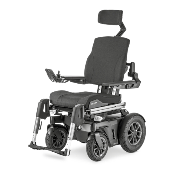
OVERVIEW Model 1.650 The overview shows the most important components and operating devices of the electric wheelchair. Pos. Description (1) Head support (2) Back support (3) Arm support (4) Seat pad (5) Leg support (6) Footplate (7) Main switch/Fuse switch (8) Steering wheel (9) Driving wheel (10) Operating module... -
Page 12: Handling The Electric Wheelchair
HANDLING THE ELECTRIC BRAKES WHEELCHAIR Brake the vehicle down carefully and in time. This is especially the case when driv- Securing the electric wheelchair ing in front of people and while driving downhill! The electric wheelchair is to be secured as follows to prevent it from rolling off unin- Service brake tentionally:... -
Page 13: Locking The Brakes
Locking the brakes It should not be possible to push the elec- tric wheelchair forward when the brakes are engaged. To engage the brakes swivel the selection lever drive-/push mode on both sides down as far as possible into drive mode [1]. ☞... -
Page 14: Drive-/Push Mode
Drive-/push mode Only switch the electric wheelchair to push mode when it is standing still for positioning or in case of emergencies, but not on slopes/hills. After push mode do not forget to switch the drive back to drive mode. Danger of uncontrolled electric wheelchair move- ment if you do not do this. -
Page 15: Selecting The Operation
SELECTING THE OPERATION In order to obtain operational readiness of the electric wheelchair the following direc- tions are to be carried out in the indicated order. ☞ Charge the drive batteries via the oper- ating module before the first journey. Selecting the motor mode. - Page 16 Check the position of the operating module. The maximum extension reached, when a mark becomes visible in the receptacle tube of the operating module. ☞ The operating module should be positioned in such a way that you can comfortably and safely steer the electric wheelchair.
-
Page 17: Pre-Operation Checks
Battery charging procedure Pre-operation checks Do not insert any objects other than the Before starting to drive, the following should battery charger plug into the battery be checked: charging socket. – Danger of short circuit! the position of the fuse switch, Only charge the batteries in well aired, dry ☞... - Page 18 Lock the electric wheelchair. ☞ Therefore observe chapter Securing the electric wheelchair on page 12. 2. Insert the charger plug into the battery charging socket (1) of the operating module. Switch the battery charger on, resp. insert the main plug of the battery charger into the corresponding power socket.
-
Page 19: Positioning The Operating Module
Positioning the operating module Switch off the operating module before adjusting/removing it. Function description You will find a detailed description of the operating elements and symbols in the op- erating manual for < Operating module >. The position of the operating module can be adjusted to suit the individual size of the user. -
Page 20: Inserting The Operating Module
Inserting the operating module Watch for possible jamming areas when plugging in the operating module. For drive mode insert the operating mod- ule from the front into the arm support tube and adjust the distance to the padded arm support. ☞... -
Page 21: Leg Support
LEG SUPPORT Before any actions on the leg support the electric wheelchair is to be secured against unintentional rolling motions. ☞ Therefore observe chapter Securing the electric wheelchair on page 12. Calf belt Do not drive without the calf belt. – Dan- ger of accidents! The removable calf belt (1) prevents the feet from sliding off the back of the footplates. -
Page 22: Lower Leg Support
Lower leg support The footplates are to be folded up for enter- ing or exiting the wheelchair [1]. ☞ Check the locking points! Remove both feet from the footplates. 2. Remove the calf belt (2), if present. ☞ Therefore observe chapter Calf belt on page 21. -
Page 23: Leg Support Upper Part
Leg support upper part The upper leg support with an inserted lower leg support is termed leg support. Turning the leg supports to the side Leg supports turned to the side are re- leased automatically and can easily come off. Note this when handling (e.g. trans- port). -
Page 24: Swivelling In The Leg Supports
Swivelling in the leg supports For inward swivelling, let the leg supports swivel forward until the lock audibly engag- es [1]. ☞ After audibly swivelling the leg sup- ports inward check the respective lock- ing device. ☞ Afterwards observe chapter Lower leg support on page 22. -
Page 25: Removing The Leg Supports
Removing the leg supports For easy transfer into and out of the electric wheelchair as well as a reduced wheelchair length (important for transport) the leg sup- ports can be removed [1]. ☞ Remove the calf belt before swivelling away the leg supports. ☞... -
Page 26: Arm Supports
ARM SUPPORTS Do not use the arm supports [1] to lift or carry the electric wheelchair. The standard arm supports [1] can be ad- justed to the requirements of the user by the specialist dealer in height, angle and length. Arm support on the back support with central connection Lowerable arm support... -
Page 27: Swivelling Up The Arm Supports
Swivelling up the arm supports As an option, the arm supports can be swiv- elled upward when desired [1]. Pull out the button (2) that locks down the arm support and swivel the arm support up as far as possible. ☞... -
Page 28: Arm Support For Round Tube Back Support
Arm support for round tube back support Do not use the arm supports [1] to lift or carry the electric wheelchair. Do not drive without the arm supports! Removing the arm support To remove the arm support, loosen the clamping screw (2) first and then pull out the arm support toward the top . -
Page 29: Back Support
BACK SUPPORT Only adjust the back support when the electric wheelchair is standing on a level surface. A danger of tipping over exists on gradients! Electrically adjustable back sup- port The angle of the back support (1) can be ad- justed through the operating module. -
Page 30: Back Support, Mechanically Adjustable
Back support, mechanically ad- justable Removing the back support upholstery For removal, first pull off the rear part of the back support cushion (1) and fold it over to the front [2]. 2. Pull the back support flap (3) off and guide it to the front. -
Page 31: Angle Adjustment
Angle adjustment The back support can be folded down for storage or transport. ☞ For better demonstration of the wire cable (1) the back support is shown without cushion. Folding down the back support ☞ If required remove the seat pad (velcro fastener). - Page 32 Secure positions of the back support Any change to the seat inclination will lead to different safe back support adjust- ments! The diverse possible seat adjustments also includes such settings, that may only be used as resting positions, since they might lead to instable driving conditions in drive mode.
-
Page 33: Head Support
HEAD SUPPORT The head support serves to support the head posture. The head support may not be positioned in the height of the neck. The upper edge of the head support should always be close to the back of the head and at about eye level. -
Page 34: Height Adjustment Of The Head Support For Round Tube Back Supports
Height adjustment of the head support for round tube back supports The maximum height adjustment is indi- cated by the marking! The head support can be detached or ad- justed in height after the clamping lever (1) has been slackened. Adjusting the head support dur- ing handicapped transport inside a motor vehicle... -
Page 35: Seat
SEAT Special safety information Only drive on slopes, inclines and ob- stacles in the basic position of the seat height adjustment and the standing resp. lying function. – Danger of overturning! Seat pad The seat pad [1] is attached to the seat plate with velcro straps and can be removed for cleaning and maintenance. -
Page 36: Seat Height Adjustment
Seat height adjustment Only operate the seat height adjustment on straight, level surfaces. – Higher danger of tilting with increas- ing seat height! Before seat height adjustment, check whether the adjustment area is free of obstacles. – Danger of injury! The seat height [1] can be adjusted through the operating module. -
Page 37: Retaining Strap
RETAINING STRAP Make sure that no objects are trapped between belt and the body! – Thus you avoid painful pressure points. The retrospective assembly of a retaining strap is only to be carried out by a special- ist workshop! The retaining strap is not part of the re- taining system for the electric wheelchair and/or the driver during transport in mo- tor vehicles. -
Page 38: Shoulder Strap
SHOULDER STRAP The shoulder strap is not part of the re- taining system for the wheelchair and/or user during transport in a motor vehicle. The shoulder strap (1) serves for additional fixation of a person sitting the wheelchair. – Additional stabilisation of the sitting position. -
Page 39: Usb Connector Socket
USB CONNECTOR SOCKET The maximum power consumption may not exceed 1 A per connection! ☞ The USB connector socket requires a permanent power supply. This may re- quire a more frequent recharging of the batteries. The USB connector socket serves to con- nect devices with a USB plug type A. -
Page 40: Rear-View Mirror
REAR-VIEW MIRROR Removing the rear-view mirror To remove the rear-view mirror loosen the clamping screw (2) and pull the rear-view mirror forward out of the arm support tube. ☞ Carefully place the rear-view mirror down and protect the mirror glass from strain or other objects. -
Page 41: Fuse Switch
FUSE SWITCH The fuse switch (1) switches the battery cur- rent of the electric wheelchair on and off. Battery current on Battery current off Antitheft safety Antitheft safety To secure against unintentional use, the fuse switch can be pulled out in the "OUT" set- ting. -
Page 42: Lighting
LIGHTING For driving outdoors and on public roads the electric wheelchair can be fit with LED-lighting equipment. The lighting is activated over the operating module for the driver. ☞ Therefore observe operation manual < Operating module >. ☞ Always switch on the lighting system in poor visibility conditions and especially during darkness in order to see better and be better seen by others. -
Page 43: Loading And Transportation
Observe the manufacturer's information further information can be accessed on for the ramp or lifting platform. our website < www.meyra.com > in the The maximum bearing height specified < Download Archive >. for the ramp must be greater than the height 'h' from the ground to the loading People transportation acc. -
Page 44: Transport Security
The specific document for the an- choring system can also be viewed in the product specific category < Operating man- uals > on our website < www.meyra.com >. Transport security All regulations and directions of the re- spective transport company are to be ob- served. -
Page 45: Tyres
TYRES Tyres are made of a rubber mixture and can leave permanent or difficult-to-remove marks on some surfaces (e.g. plastic, wood- en or parquet flooring, carpets, mats). We cannot accept liability for damages on sur- faces caused by wear or chemical processes of the tyres. -
Page 46: Maintenance Schedule
Maintenance schedule WHEN WHAT REMARK Before starting out General Carry out test yourself or with a helper. Test for faultless operation. Checking the magnet- Carry out test yourself or with ic brake a helper. Move the selection lever If the electric wheelchair can for the drive/push mode be pushed, have the brakes into the drive mode posi-... - Page 47 WHEN WHAT REMARK Every 6 -8 months Wheel attachments Do it yourself or with the aid (depending dis- of a helper. Wheel nuts or screws are tance covered) to be checked for tight fit. Securely tighten any loosened wheel nuts or screws and retighten again after 10 oper- ating hours or resp.
-
Page 48: Fuses
Fuses Replacing the fuses Only have the mains-/battery fuse re- placed by a specialist dealer. ☞ Therefore observe chapter Technical data on page 57. -
Page 49: Lighting
Lighting Have a defective lamp repaired immedi- ately. The lighting (1)+(2) is equipped with longlife LED-technology. ☞ If a turn-signal bulb is defective, the re- maining one blinks at double frequen- Headlights The housing of the light (1) must be adjust- ed so that the light cone is visible on the driving surface. -
Page 50: Fault Correction
Fault correction Fault Cause Remedy Battery indicator on the Battery fuse is defective or Have it repaired by the operating module does not correctly inserted. specialist workshop. not light up after the switch-on. Plug connection of the Check the plug connec- power supply without... -
Page 51: Basic Safety Information
Prevent such heating by that can be found on our website: < www. parking the electric wheelchair in a shad- meyra.com >. ed area. Never reach into the swivel area of the Special receptacle point for the attach-... -
Page 52: Reaching For Objects
Reaching for objects quired immediately bring the joystick back into the neutral position. Avoid an extreme forward or backward in- Never drive faster than walking speed. clination of the upper body when picking up or placing heavy objects. – Danger of The braking force transferred to the driving electric wheelchair tipping over, especially surface is much less on a downward slope... -
Page 53: Electrical System
Transport in public methods of es. Cross the obstacle forwards with about 0.5 m approach and simultaneously with transportation both front- resp. rear wheels. Otherwise Your electric wheelchair is not designed for your electric wheelchair could tilt diago- user transport in public transportation vehi- nally and you could fall out of the electric cles. -
Page 54: Driving On Public Highways
CLEANING Driving on public highways Observe the valid regulations for public traf- The plastic panelling is attacked through fic of your country and if necessary ask your non-ionic tensides as well as solvents and specialist dealer for required accessories. especially alcohol. Your electric wheelchair can optionally be Do not clean the electric wheelchair with fit with lighting equipment. -
Page 55: Finish
< Information center > on our national facility for health protection. website: ☞ During the use of disinfectants it can < www.meyra.com >. happen that surfaces might be affect- ed in such a fashion that the long term Finish functionality of parts can be limited. -
Page 56: Customer Service
Customer Service Information for extended pauses of use In case you have any questions or need help please contact your specialist dealer who In case of longer periods without use, the can assume counselling, customer service following measures are required: and repairs. -
Page 57: Technical Data
TECHNICAL DATA Maximum range The nominal values indicated by are reason- All data given in the < Technical data > refers able in compliance with ISO 7176-4. to the standard version. The maximum range depends to a large ex- tent on the following factors: Dimensional tolerance ±15 mm, ±... -
Page 58: Hill Climbing Ability
Hill climbing ability Gradients in excess of the permitted values (e.g. ramps) should for safety reasons only be driven when the wheelchair is empty! Applied norms The electric wheelchair complies with the norm: – EN 12184: 2014 – ISO 7176-8: 2014 –... -
Page 59: Values Acc. To Iso 7176-15 For Model 1.650 Ichair Meylife
Values acc. to ISO 7176-15 for model 1.650 iCHAIR MEYLIFE min. max. Overall length with leg supports 1120 mm 1220 mm (measured in the center sitting position) Overall width 600 mm 820 mm Overall dimensions – kg 370 kg User weight (incl. additional load) –... -
Page 60: Further Technical Data For Model 1.650 Ichair Meylife
Values acc. to ISO 7176-15 for model 1.650 iCHAIR MEYLIFE min. max. Obstacle height – mm 70 mm Minimal turning radius 940 mm – mm (normative recommendation according to ISO 1000 mm) Forward top speed (depending on equipment) 6 km/h... - Page 61 Further technical data for model 1.650 iCHAIR MEYLIFE min. max. Width 600 mm 820 mm Height without head support (the central back sup- 590 mm 1150 mm port cannot be folded onto the seat) Climatic data Ambient temperature -25 °C to +50 °C Storage temperature with drive batteries -25 °C to +50 °C...
-
Page 62: Meaning Of The Labels On The Electric Wheelchair
Meaning of the labels on the electric wheelchair Attention! Read the operating manuals and other provided documenta- tion. Do not lift the electric wheelchair at the arm supports or leg supports. Removable parts are not suitable for carrying. Drive mode Push mode Push only on level surfaces. -
Page 63: Meaning Of The Symbols On The Washing Instruction
Meaning of the labels on the electric wheelchair Attention! Do not conduct maintenance jobs. Gas pressure container of the pneumatic spring is under pres- sure. – Increased danger of accident! Meaning of the symbols on the washing instruction (the symbols correspond to European standard) Wash as delicates with the indicated maximum temperature in °C. -
Page 64: Meaning Of The Symbols On The Type Plate
Meaning of the symbols on the type plate Manufacturer Order number Serial number Production date Permitted user weight max. permissible total weight Permitted axle weights Max. permissible rising gradient Max. permissible falling gradient Permitted maximum speed The product is approved as a seat within a motor vehicle. Max. -
Page 65: Inspection Certificate
INSPECTION CERTIFICATE Recommended safety inspection 1st year (at least every 12 months) Electric wheelchair data: Stamp of specialist dealer: Model: Signature: Delivery note no.: Place, date: Serial-no.(SN): Next safety inspection in 12 months Date: Recommended safety inspection 2nd year Recommended safety inspection 3rd year (at least every 12 months) (at least every 12 months) Stamp of specialist dealer:... -
Page 66: Warranty / Guarantee
< Information center > sector < PMS > on following Warranty/Guarantee section and our website < www.meyra.com >. the there included information on model We reserve the right to make technical im- description, delivery note number with de- provements. -
Page 67: Warrantee / Guarantee Section
Warrantee / Guarantee section Please fill out! Copy if necessary and send the copy to the specialist dealer. Warranty / Guarantee Model designation: Delivery note no.: SN (view type plate): Date of delivery: Stamp of the specialist dealer: Inspection certificate for transfer Electric wheelchair data: Serial-no.(SN): Stamp of specialist dealer:... - Page 68 Your specialist dealer MEYRA GmbH Meyra-Ring 2 32689 Kalletal Kalldorf GERMANY +49 5733 922 - 311 +49 5733 922 - 9311 info@meyra.de www.meyra.de 205 348 501 (Status: 2021-05) All technical modifications reserved. Original operating manual.
Need help?
Do you have a question about the 1.650 iCHAIR MEYLIFE and is the answer not in the manual?
Questions and answers